CP40 service manual.pdf - 第96页
1. Head Part (CP-40) 1-3-7. CA => WA Change 1. Prep aration Version Date WA QA CA Note 00 Nov04 O O Material Refer to Attached Materials. S/W MMI INSTALL CD Tool Cross and F lat-head Screwdrivers (Large, S mall), Digi…
1. Head Part
(CP-40)
1-3-6. WA Cleaning Method
<Installation State and Abandonment Rate>
If WD-40 or Glass Cleansing Fluid is Applied to W/A Aligner Sensor, Diffuser Film and Cover Glass Adhesive are Dissolved. If
User Applies Vinyl Tape to Aligner Window Optionally, Inferiority of Installation State and Abandonment Rate may be Caused.
<WA Cleaning Method>
1. W/A Cleaning
Because W/A Diffuser and Cover Glass are Exposed, They Should be Maintained
Cleanly. Fingerprint or Dust may Influence Installation State.
2. Cycle
1) Diffuser : Once a Month
2) Cover Glass : Every Third Week
3) Besides the Above Cycles, Perform Cleaning When Abandonment Rate of Part
is Increased and Installation State is Bad.
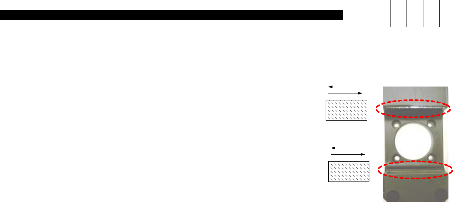
3. Method
1) Diffuser : Using Soft and Dry Cotton Cloth, Wipe Gently in the Same Direction with Pattern..
# Caution : Never Use Solvent such as Water, Alcohol, Glass Cleansing Fluid, etc.
Only Use Dry Cloth.
2) COVER GLASS :
- Using Soft and Dry Cotton Cloth, Wipe Gently in the Same Direction.
-
If Foreign Materials are still Left, Wipe Gently in the Same Direction with Soft and Dry Cotton Cloth Applied with a little Ethyl Alcohol.
- Using Soft and Dry Cotton Cloth, Remove Residual Ethyl Alcohol(Wipe in the Same Direction).
# Caution : (1)
If Wiping in the Both Directions, Foreign Materials may not be Removed or Damage to Glass may be Caused.
(2) Never Use Any Solvent except for Ethyl Alcohol.
Version Date WA QA CA Note
00 Nov04 O
1. Head Part
(CP-40)
1-3-7. CA => WA Change
1. Preparation
Version Date WA QA CA Note
00 Nov04 O O
Material Refer to Attached Materials.
S/W MMI INSTALL CD
Tool Cross and Flat-head Screwdrivers(Large, Small), Digital Tester
<Procedures>
1. Commonly Usable Part
a. Brackets of Cyber Aligner and Woori Aligner on the Front Middle Plate (with Fixing Hole)
(When Used Commonly, WA Bracket is Attached to the Position with CA I/F Board Removed)
b. Power Supply Middle Plate of CA and WA
c. For CP40CV Equipment, CE is not Added Newly and there is no Additional Items to Wago Terminal.
(Only WA is Attached to CA Equipment and CE Part is not Changed.)
2. Part to be Changed (Equipment Modification Method)
a. Remove the Material Shown in 40_CA Removal of this Document from the Equipment(25 Sorts).
(Part to be Excepted from CP40CV Equipment)
b. Prepare to Attach the Material Shown in 40_WA Addition of this Document to Equipment(17 Sorts)
.
(Material to be Added to CP40CV Equipment)

1. Head Part
(CP-40)
3
.
Working Method
a. Remove Cyber Aligner Cable of Cableveyor and Attach WA(WOORI) Aligner Cable.
b. Remove Cyber Aligner Board and Remove Bracket and Wiring.
c. Remove 'IP501' of VME162 Board and Attach 'Octal Card' (Remove Cable Connected to IP Card).
d. Remove Cable 'CA2-VM10-1' Connected with QA I/F Board and R Motor Driver from Axis Board H1/2/3.
e. Remove 'VSF100-24' Power Supply for CA from Power Supply Middle Plate and Attach Power Supply 'SA100-BDB' for
WA(WOORI).
f. Remove CA I/F Board and Adjacent Cable.
g. Connect Power Cable From Power Supply to Front T/B2.
h. Attach WA Bracket, Attach Board and Connect Wire.
(
Wa Aligner Wiring Block Diagram
)
4. MMI Installation
5. Profile Setting
- Refer to Line Profile Optimization Setting Method for SI(20030711T)CP-204050.
Version Date WA QA CA Note
00 Nov04 O O