Specification SIPLACE X-Series规格说明书2 - 第18页
18 Placement Heads Nozzle Changers Technical Data The number of nozzle changers for the Collect & Place heads depe nds on the number of gantries in the placement area: - up to four nozzle changers may be installed in…
17
Placement Heads
Nozzle Changers
Description
Nozzle changers increase
the flexibility of placement
heads when processing dif-
ferent components. The
nozzle configuration can be
quickly modified for new
placement jobs. Exactly
defined positions and the per-
fect seating of the nozzle in
the garage guarantee mini-
mal radial eccentricity at the
placement head.
The nozzle changers for the
MultiStar and the SpeedStar
are equipped with a monitor-
ing circuit which checks
whether the nozzle magazine
is seated correctly on the
mount. The nozzle changer
also detects from the coding
whether it is a magazine for
1xx, 20xx or 28xx nozzles.
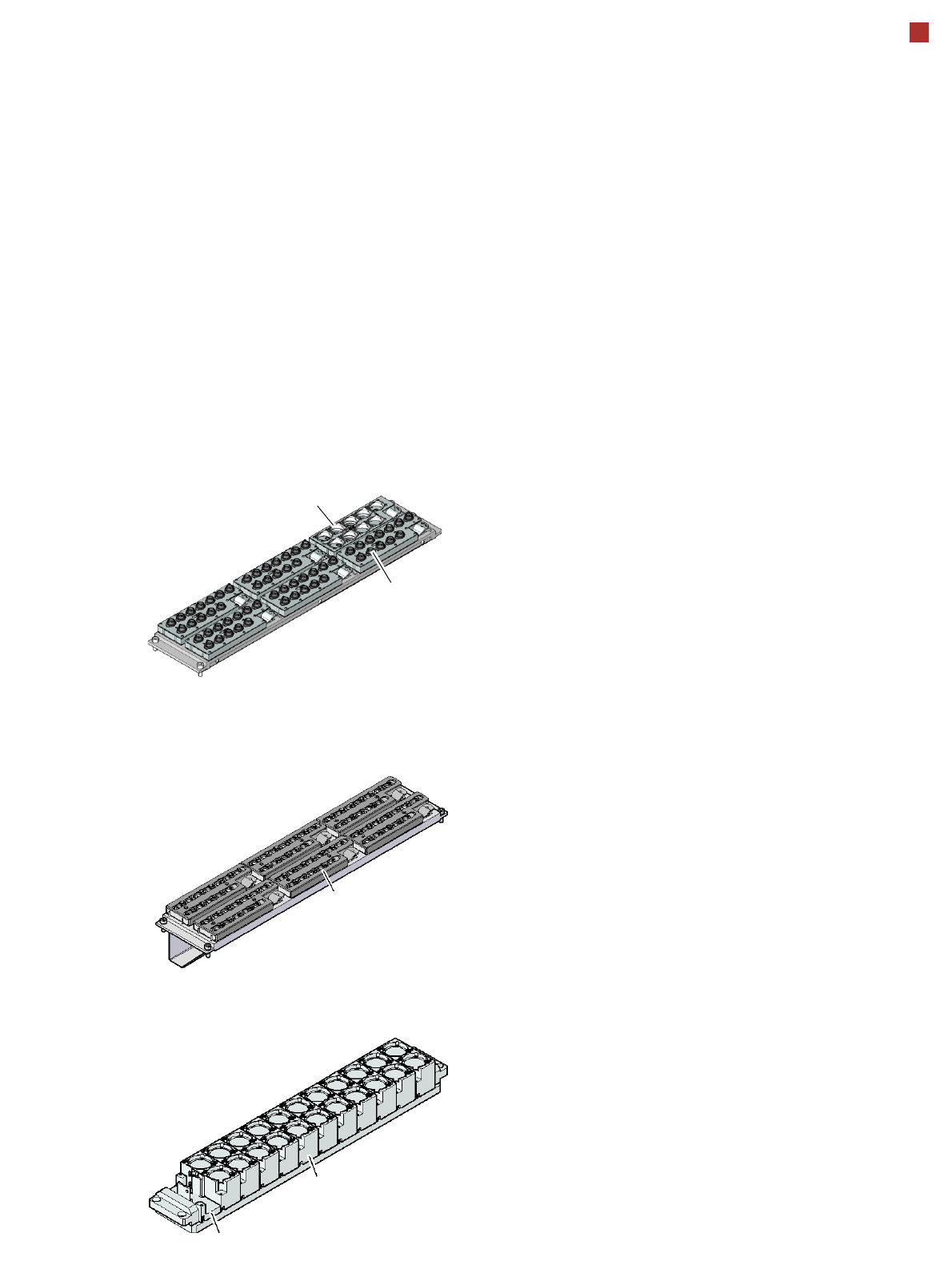
Nozzle changers for the MultiStar and SpeedStar (PWCPP)
Standard configuration:
SIPLACE MultiStar: 5 magazines for 20xx nozzles
(60 nozzle holders) and
1 magazine for 28xx nozzles
(9 nozzle holders)
SIPLACE SpeedStar: 6 magazines (72 nozzle holders)
Magazine for two
standard nozzles
Magazine for one special nozzle, gripper
Nozzle changers for the SIPLACE TwinStar (PWTH)
Magazine for 9
type 28xx nozzles
Magazine for 12
type 20xx nozzles
Nozzle changers for the SIPLACE SpeedStar (PW20)
6 magazines 72 nozzle holders)
Magazine for 12
type 10xx, 11xx or 12xx nozzles

18
Placement Heads
Nozzle Changers
Technical Data
The number of nozzle changers for the Collect&Place heads depends on the number of gantries
in the placement area:
- up to four nozzle changers may be installed in the placement area with two gantries
- up to three nozzle changers may be installed in the placement area with one gantry
Nozzle changers for the SIPLACE SpeedStar (PW20)
Dimensions (length x width x height) 449 x 94.5 x 79 mm³
Number of magazines 6
a,b
a) All 6 magazines must always be set up.
b) SIPLACE X4I: 4 active magazines at location 2 and 4.
Number of nozzle holders 72
Nozzle types 10xx, 11xx, 12xx
Compressed air connection 0.48 MPa (4.8 bar)
Nozzle changers for the SIPLACE MultiStar (PWCPP)
Dimensions (length x width x height) 449 x 62.7 x 77.7 mm³
Number of magazines 6
a, b
Number of nozzle holders MultiStar: 60 20xx nozzles
9 28xx nozzles
SpeedStar: 72 10xx, 11xx, 12xx nozzles
Nozzle types MultiStar: 20xx, 28xx
SpeedStar: 10xx, 11xx, 12xx
Compressed air connection 0.48 MPa (4.8 bar)
Nozzle changers for the SIPLACE TwinStar (PWTH)
Dimensions (length x width x height) 448 x 68.5 x 49 mm³
Number of magazines a maximum of 12, each with two nozzle holders at
locations 1 and 3
a maximum of 10, each with two nozzle holders at
locations 2 and 4
Number of nozzle holders may be freely configured
Nozzle types 4xx with adapter
5xx (standard)
9xx with adapter
Special nozzle, gripper
19
PCB Conveyor
Single Conveyor And Flexible Dual Conveyor
Conveyor principle
If the board has reached the
placement area and passed
a light barrier, it is braked. An
additional laser light barrier
determines the position of
the board. As soon as the cir-
cuit board has reached its
target position, the conveyor
belt is stopped and the board
is clamped from below. The
placement process then
starts immediately. Move-
ment and clamping of the
PCBs are monitored.
Position of the conveyor
rails
The conveyor can be easily
matched to many different
PCB widths by the automatic
electrical width adjustment.
The fixed conveyor rail may
be located on the left or right
for both the flexible dual con-
veyor and the single con-
veyor.
Conveyor buffer
SIPLACE PCB conveyors
have three buffer zones (see
figure, page 9. If shorter wait-
ing times occur in a place-
ment area (due to longer
cycle times in the oven, for
example), the downstream
placement areas can con-
tinue to work since the unaf-
fected area can easily
access the PCB that is wait-
ing in the buffer zone. This
increases the true output of
the placement line.
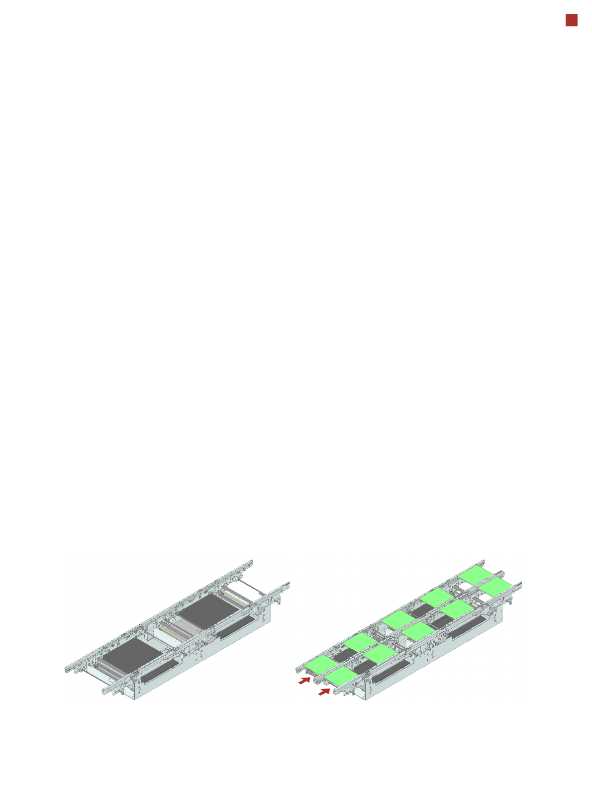
Single conveyor
On the single conveyor,
PCBs are moved one after
the other into the placement
machine and placed on a
conveyor lane. This con-
veyor variant is particularly
suitable for very wide PCBs.
Flexible dual conveyor
To keep the range of PCBs to
be processed as wide as
possible - whilst maintaining
maximum productivity - the
flexible SIPLACE dual con-
veyor allows you to choose
between single conveyor
mode and dual conveyor
mode. In dual conveyor
mode, two PCBs are moved
into the placement machine
and placed either simultane-
ously (synchronous opera-
tion) or alternately (asyn-
chronous operation).
In synchronous mode, two
PCBs are moved into the
placement position at the
same time. They are pro-
cessed as a common panel.
This allows the top and bot-
tom of PCB to be processed
on the same line and, for
products with very different
components to be placed,
the common optimization of
all the components to be
placed on both PCBs makes
it possible to increase output.
Single conveyor
Flexible dual conveyor:
synchronous mode