Specification SIPLACE X-Series规格说明书2 - 第20页
20 PCB Conveyor Alternating Placement Mode SIPLACE X4I I-Placement In asynchronous mod e , only one PCB in a transport lane is processed. At the same time, anothe r PCB in the second transport lan e is moved into the p l…
19
PCB Conveyor
Single Conveyor And Flexible Dual Conveyor
Conveyor principle
If the board has reached the
placement area and passed
a light barrier, it is braked. An
additional laser light barrier
determines the position of
the board. As soon as the cir-
cuit board has reached its
target position, the conveyor
belt is stopped and the board
is clamped from below. The
placement process then
starts immediately. Move-
ment and clamping of the
PCBs are monitored.
Position of the conveyor
rails
The conveyor can be easily
matched to many different
PCB widths by the automatic
electrical width adjustment.
The fixed conveyor rail may
be located on the left or right
for both the flexible dual con-
veyor and the single con-
veyor.
Conveyor buffer
SIPLACE PCB conveyors
have three buffer zones (see
figure, page 9. If shorter wait-
ing times occur in a place-
ment area (due to longer
cycle times in the oven, for
example), the downstream
placement areas can con-
tinue to work since the unaf-
fected area can easily
access the PCB that is wait-
ing in the buffer zone. This
increases the true output of
the placement line.
Single conveyor
On the single conveyor,
PCBs are moved one after
the other into the placement
machine and placed on a
conveyor lane. This con-
veyor variant is particularly
suitable for very wide PCBs.
Flexible dual conveyor
To keep the range of PCBs to
be processed as wide as
possible - whilst maintaining
maximum productivity - the
flexible SIPLACE dual con-
veyor allows you to choose
between single conveyor
mode and dual conveyor
mode. In dual conveyor
mode, two PCBs are moved
into the placement machine
and placed either simultane-
ously (synchronous opera-
tion) or alternately (asyn-
chronous operation).
In synchronous mode, two
PCBs are moved into the
placement position at the
same time. They are pro-
cessed as a common panel.
This allows the top and bot-
tom of PCB to be processed
on the same line and, for
products with very different
components to be placed,
the common optimization of
all the components to be
placed on both PCBs makes
it possible to increase output.
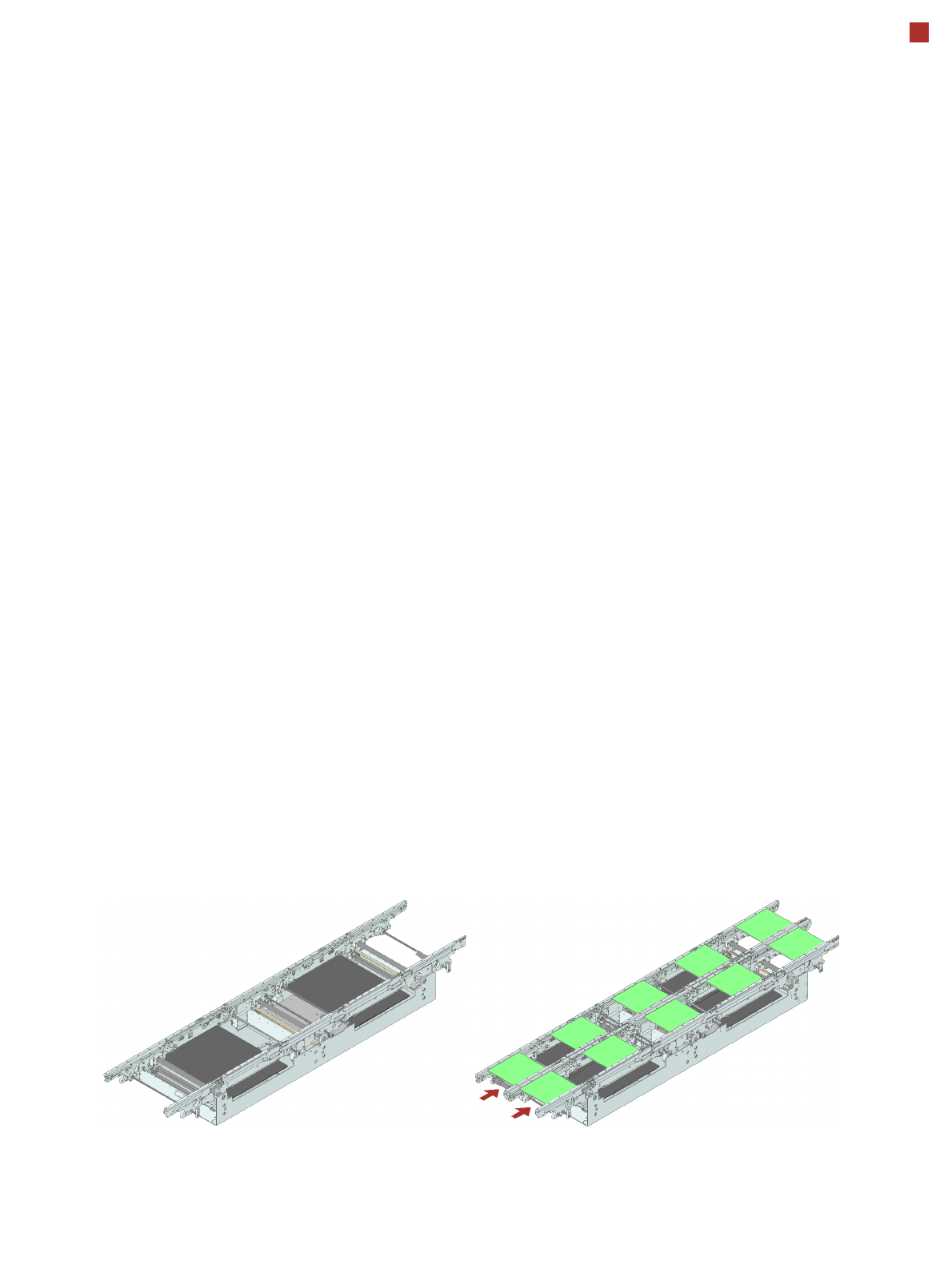
Single conveyor
Flexible dual conveyor:
synchronous mode
20
PCB Conveyor
Alternating Placement Mode
SIPLACE X4I I-Placement
In asynchronous mode,
only one PCB in a transport
lane is processed. At the
same time, another PCB in
the second transport lane is
moved into the placement
position. This saves the full
conveying time of one PCB,
thus considerably increasing
performance, particularly for
PCBs with a short cycle time.
The placement process
starts as soon as one PCB is
transported into the process-
ing area.
Alternating placement
mode
In the proven SIPLACE
placement method, the two
heads work alternately on
the PCBs on both conveyor
lanes. While the first head is
placing components on both
PCBs, the other head picks
up new components. With
this new arrangement of the
placement heads and com-
ponent changeover table in
SIPLACE X4I, the output is
much higher in both con-
veyor modes than in a com-
parable SIPLACE X4.
I-Placement
(SIPLACE X4I only)
Another placement concept
has been developed for the
SIPLACE X4I in addition to
synchronous and asynchro-
nous modes. This is known
as I-placement. In this mode,
the two heads work simulta-
neously and populate a PCB
totally independently of one
another. This further in-
creases the output. The
background: the placement
heads and component
feeder modules from the
SIPLACE X-series have
speeded up component pick-
up to such an extent that it is
now the distance compo-
nents are transported to the
PCB that is the speed-limit-
ing factor.
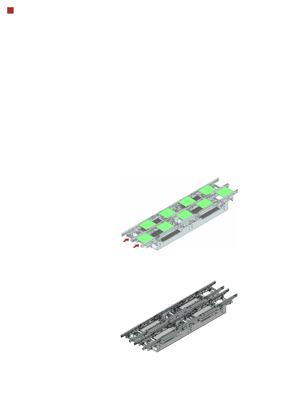
Flexible dual conveyor:
asynchronous mode
Flexible dual conveyor
SIPLACE X4I:
Set for I-placement.
Distance between outer sta-
tionary conveyor edges:
535 mm.

21
SIPLACE X4/X3/X2 PCB Conveyor
Technical Data
Single conveyor Flexible dual
conveyor
Dual conveyor in
Single conveyor mode
Fixed conveyor side Right or left Right or left Right or left
Standard dimensions
(length x width)
50 x 50 mm² to
450 x 535 mm²
a
a) With PCB widths > 450 mm make sure that the peripheral modules are also able to process these
widths.
50 x 50 mm² to
450 x 250 mm²
50 x 50 mm² to
450 x 450 mm²
Long board option 50 x 80 mm² to
610 x 535 mm²
50 x 80 mm² to
610 x 250 mm²
50 x 80 mm² to
610 x 450 mm²
PCB thickness Standard: 0.3 mm to 4.5 mm (others available on request)
PCB warpage see page 25
PCB weight max. 3 kg
Clearance on PCB under-
side
25 mm ± 0.2 mm (standard)
PCB transport height 830 mm ± 15 mm (option)
900 mm ± 15 mm (option)
930 mm ± 15 mm (standard)
950 mm ± 15 mm (SMEMA option)
Type of interface SMEMA / Siemens
b
b) Option.
Component-free PCB
handling edge
3 mm
PCB changeover time < 2.5 s
PCB positioning accuracy ± 0.5 mm
Flexible dual conveyor Conveyor mode: synchronous or asynchronous (selected via the soft-
ware)
Components to be placed on each conveyor lane: same or different
PCB width on each conveyor lane: same or different
Bad fiducial detection Single conveyor: standard
Synchronous dual conveyor: standard (no global ink spot)
Asynchronous dual conveyor: standard
Automatic electrical width
adjustment
Single conveyor: standard
Synchronous dual conveyor: standard
Asynchronous dual conveyor: standard