Specification SIPLACE X-Series规格说明书2 - 第24页
24 SIPLACE X4I/X4 PCB Conveyor SIPLACE Quad Lane Conveyor Description The quad lane conveyor can be installed on SIPLACE X4I and SIPLACE X4 placement machines. This allows up to four PCBs to b e processe d at the same ti…
23
PCB Conveyor
SIPLACE X4I I-Placement
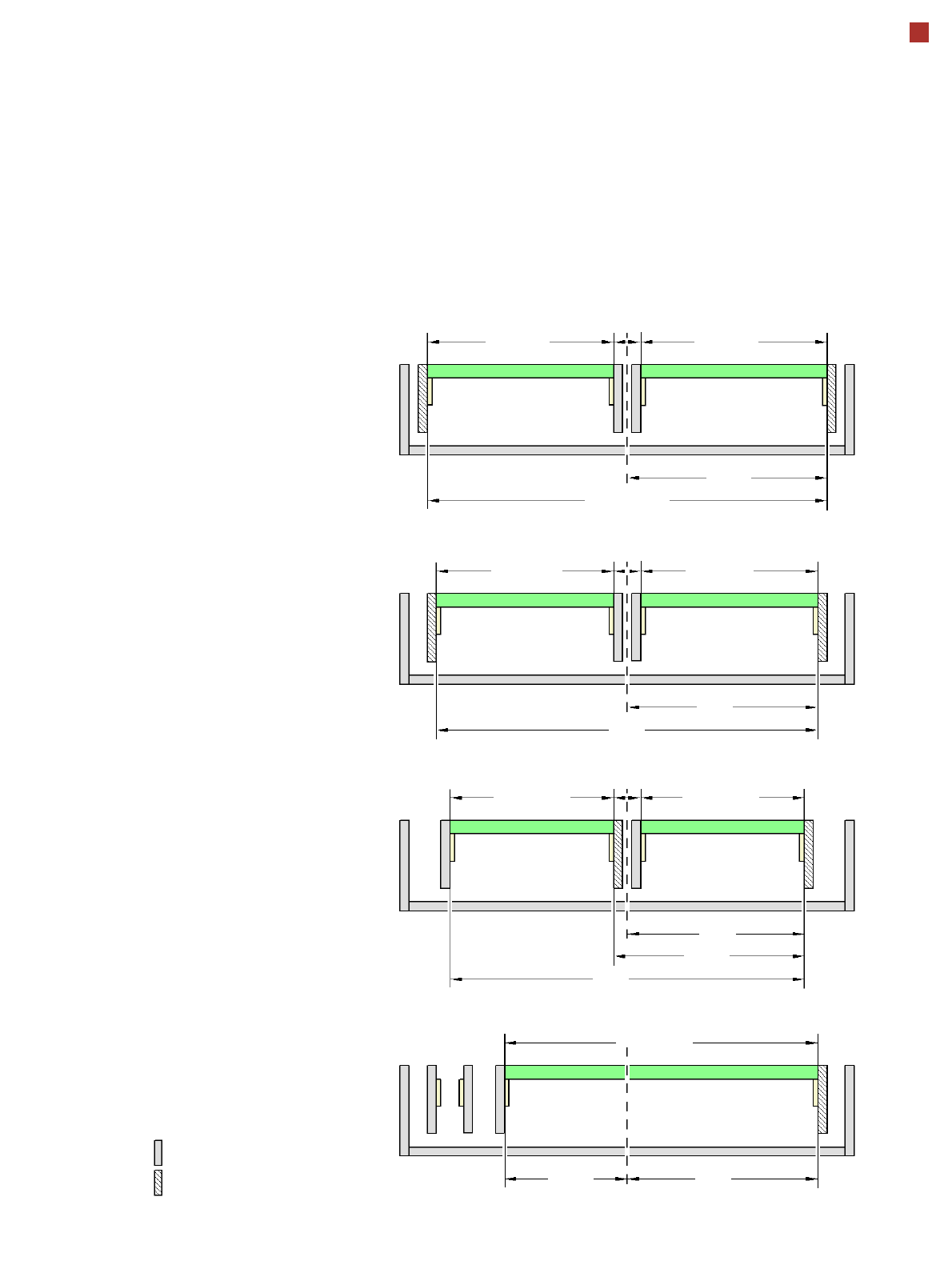
X4I/X4/X3/X2 Alternating Placement Mode
Alternating or
I-placement
a
mode
Distance between outer con-
veyor edges: 535 mm, 2 lanes,
stationary outer conveyor edge
Alternating or I-placement
a
mode
Distance between outer con-
veyor edges: 508 mm, 2 lanes,
stationary outer conveyor edge
Alternating placement mode
Distance between outer con-
veyor edges: 468 mm, 2 lanes,
right conveyor edges are
stationary
b
Alternating placement mode
Distance between outer con-
veyor edges: 508 mm, dual con-
veyor in Single conveyor mode,
right conveyor edge is
stationary
b
max. 250
Movable conveyor side
Stationary conveyor side
a) For SIPLACE X4I only.
b) Only settings with stationary conveyor edge on the right are shown. A setting with the stationary conveyor edge on the left
is also possible. All dimensions in millimeters.
c) Widths up to 450 mm are possible for SIPLACE X4/X3/X2. In this case, the distance between outer conveyor edges is 535
mm.
max. 250
267.5
535
min. 35
max. 236.5
254
508
min. 35 mm
max. 236.5
254
182.5
max. 216.5
234
min. 35
max. 216.5
251.5
468
max. 436.5
c
24
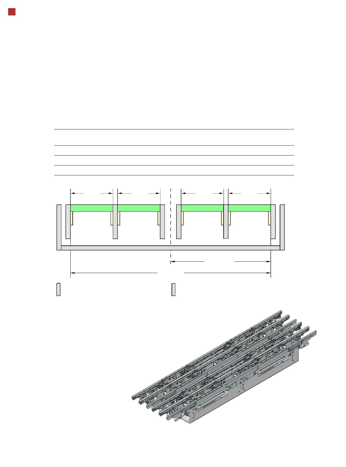
SIPLACE X4I/X4 PCB Conveyor
SIPLACE Quad Lane Conveyor
Description
The quad lane conveyor can
be installed on SIPLACE X4I
and SIPLACE X4 placement
machines. This allows up to
four PCBs to be processed at
the same time on this con-
veyor.
Conveyor lanes 1R and 1L or
2R and 2L carry the PCBs in
synchronous mode, while
the two conveyor lane
groups 1 and 2 can trans-
port the PCBs in both syn-
chronous and asynchronous
mode. On the quad lane con-
veyor, the two outer con-
veyor rails are stationary.
The conveyor can be config-
ured as a 1-lane, 2-lane or 4-
lane conveyor using the soft-
ware without making
any changes to the
hardware.
Technical data
Conveyor mode PCB width
lane 1R [mm]
PCB width
lane 1L [mm]
PCB width
lane 2R [mm]
PCB width
lane 2L [mm]
SIPLACE Quad Lane max. 114 max. 114 max. 114 max. 114
Quad Lane in Dual lane mode max. 178.5 max. 178.5
Quad Lane in Single lane mode max. 306.5
Max.
114 mm
267.5 mm
535 mm
Movable conveyor sideStationary conveyor side
Max.
114 mm
Max.
114 mm
Max.
114 mm
Lane 2L Lane 2R Lane 1L Lane 1R
25
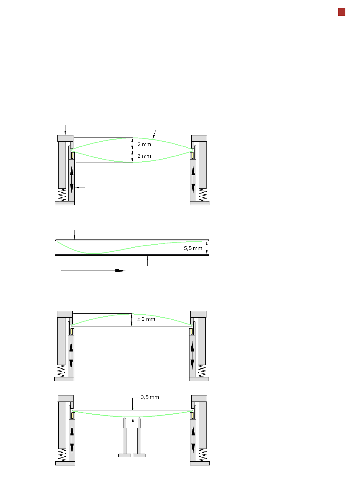
PCB Warpage
PCB warpage across the direction of travel
max. 1 % of the PCB diagonal, but not ex-
ceeding 2 mm
PCB warpage on the conveyor
PCB warpage during placement
PCB transport direction
PCB warpage down, max. 0.5 mm
Use magnetic pin supports to achieve this
value.
Conveyor belt
Fixed clamped edge
PCB warpage in direction of travel
+ PCB thickness < 5.5 mm
Fixed clamped edge
Movable clamping device
For warpage of less than 2 -mm, the ink
spots are also in the middle of the PCB in
the digital camera's focus. When all the tol-
erances are taken into account, this value is
reduced to 1.5 mm.
You should also note that the warpage re-
duces the component height.
Magnetic pin support
PCB