Specification SIPLACE X-Series规格说明书2 - 第33页
33 Digital SIPLACE Vision System The digital vision system guarantees extremely fast and reliable component re c- ognition, while being ver y simple to use. The system identifies each individual component from its shape …

32
Component Feeding
Matrix Tray Changer (MTC)
Technical Data
Electrical ratings
Tray supply 1 (XL) Tray supply 2
Dimensions
Length x width
Height
1305 x 600 mm²
1490 mm for 830 mm PCB transport height
1560 mm for 900 mm PCB transport height
1590 mm for 930 mm PCB transport height
1640 mm for 950 mm PCB transport height
Weight (basic equipment)
approx. 500 kg (with PCB magazines and waffle-pack tray carriers)
Weight (fully equipped)
approx. 534 kg (with components)
Weight (moving mass)
approx. 80 kg approx. 43.5 kg
Cassette size (L x W x H)
391.2 x 305.6 x 93.3 mm³ 352.7 x 154.8 x 133.8 mm³
Cassette weight
(fully equipped)
(without waffle-pack tray carrier)
approx. 11 kg
approx. 1.7 kg
approx. 7.5 kg
approx. 1.35 kg
Weight of the
waffle-pack tray carrier
850 g 150 g
Dimensions of the waffle-pack
tray carrier (L x W x H)
386.5 x 295.8 x 11.1 mm³ 371 x 146 x 10.1 mm³
Distance from cassette to cas-
sette
96 mm 135 mm
Distance from level to level
12 mm 11.8 mm
Storage capacity
30 XL waffle-pack tray carriers
with 60 JEDEC or
30 special magazines
of maximum size
40 waffle-pack tray carriers with
40 JEDEC
waffle-pack trays
Changeover time (over 5 levels)
approx. 2 s approx. 1.5 s
Max. height of component and
waffle-pack tray, including toler-
ances
all levels filled
one level free
two levels free
8.5 mm
19.5 mm
31.5 mm
8.5 mm
19.5 mm
–
Supply voltage 3 x 400 VAC, 50 Hz (Europe)
3 x 208 VAC, 60 Hz (USA)
Total power 1.5 kW
Apparent power 3.85 kVA
Rated current 2.7 A at 3 x 400 VAC
4.2 A at 3 x 208 VAC
Fuses 3 x 16 A
Rated power consumption
of the largest consumer
2 A

33
Digital SIPLACE Vision System
The digital vision system
guarantees extremely fast
and reliable component rec-
ognition, while being very
simple to use. The system
identifies each individual
component from its shape
and color. Even complex
component shapes, such as
flip-chip or CCGA are
detected extremely reliably.
The system is not only used
in the placement head cam-
eras; it can also be found in
the PCB camera. As well as
ensuring that components
are detected accurately, it
also ensures reliable detec-
tion of the ink spots and PCB
fiducials.
The benefits at a glance:
• Extremely fast and reliable
component detection
• Shortest cycle times
• Robust measurement with
reference to the shape
and color
• Straightforward program-
ming
• Offline programming of
package forms
• Rapid introduction of new
products (NPI)
• Open architecture allows
you to quickly adapt to
new requirements
• Optimum placement
results through individual
measurement of each
component
Digital vision cameras
SIPLACE SpeedStar camera, type 23
SIPLACE MultiStar camera, type 30
SIPLACE TwinStar camera, type 33 (standard)
SIPLACE TwinStar high resolution camera, type 25
SIPLACE PCB camera, type 34 (standard)
Examples of digital vision system analysis times
Analysis times are only important for the P&P process.
01005 9 ms
PLC44 17 ms
BGA 225 balls 18 ms
The SIPLACE vision system
provides testing routines and
functions that increase the
component recognition qual-
ity.
The benefits at a glance:
• Maximum placement
quality
• High first pass yield
• Reduced operating costs
34
Digital SIPLACE Vision System
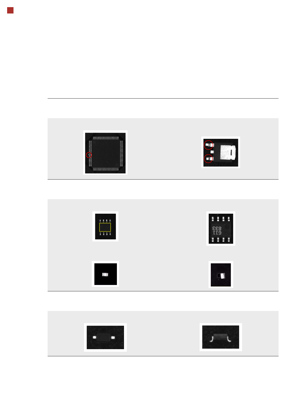
Checking the Component Quality
Overview of the Most Important Functions
Detecting collinearity of the leads
Damaged or bent leads are detected,
thus avoiding unsoldered connections during the subsequent soldering process.
Damaged leads
Detecting flipped (face-down) or standing components
Flipped (face-down) or standing components are detected
on both chip and IC models (e.g. SOT).
SOT OK SOT face-down
Chip flipped Chip standing
Checking the lead width
The optical check of the lead width detects sloping or damaged leads.
This allows diodes with sloping leads, for example, to be detected.
Lead width OK Sloping lead