Specification SIPLACE X-Series规格说明书2 - 第50页
50 Technical Data SMEMA Interface Signal Sequence 1. After swit ching on t he statio n Transport direction Belt n Belt n+1 PCB sensor PCB sensor Station n transports PCB to the transfer position Belt n running Belt n+1 s…

49
Technical Data
SMEMA Interface
Connector Assignment
Signal interface (14-pole connecting socket, interface standard 1.2)
Upstream station X1 Downstream station X2
Pin 1 NOT READY + Pin 1 NOT READY +
Pin 2 NOT READY – Pin 2 NOT READY –
Pin 3 BOARD AVAILABLE + Pin 3 BOARD AVAILABLE +
Pin 4 BOARD AVAILABLE – Pin 4 BOARD AVAILABLE –
Pin 5 Not used Pin 5 Not used
Pin 6 Not used Pin 6 Not used
Pin 7 Not used Pin 7 Not used
Pin 8 Reserved Pin 8 Reserved
Pin 9 Reserved Pin 9 Reserved
Pin 10 Reserved Pin 10 Reserved
Pin 11 Reserved Pin 11 Reserved
Pin 12 Reserved Pin 12 Reserved
Pin 13 Reserved Pin 13 Reserved
Pin 14 Reserved Pin 14 Reserved
50
Technical Data
SMEMA Interface
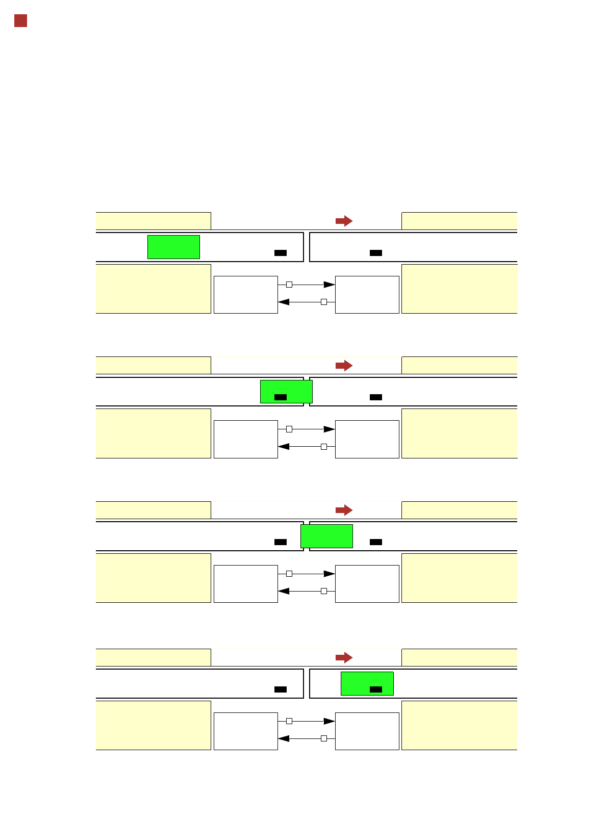
Signal Sequence
1. After switching on the station
Transport direction
Belt n Belt n+1
PCB sensor PCB sensor
Station n transports PCB
to the transfer position
Belt n running Belt n+1 stopped
BOARD AVAILABLE
Permission
Station n+1
is not ready
1
0
2. The PCB transfer has started
Transport direction
Belt n Belt n+1
PCB sensor
Station n transfers
PCB to Station n+1
Belt n running Belt n+1 running
Station n+1 expects
PCB from station n
3. PCB is transferred
Transport direction
Belt n Belt n+1
PCB sensor PCB sensor
Station n has
just transferred the PCB
Belt n stopped Belt n+1 running
Station n+1 expects PCB
from station n, but PCB
has not yet arrived.
PCB sensor
4. PCB transfer is complete
Transport direction
Belt n Belt n+1
PCB sensor PCB sensor
Station n
Belt n stopped Belt n+1 running
Station n+1
PCB arrived
Request
NOT READY
BOARD AVAILABLE
Permission
1
1
Request
NOT READY
BOARD AVAILABLE
Permission
0
1
Request
NOT READY
BOARD AVAILABLE
Permission
0
0
Request
NOT READY
To start a new PCB transfer, both signals must be “0” for at least 50 ms.

51
Technical Data
Siemens Signal Interface
Connector Assignment
Signal interface (20-pin ribbon cable connector)
Upstream station X1 Downstream station X2
Pin 1 Reserved Pin 1 Reserved
Pin 2 GND 24 VDC Pin 2 Reserved
Pin 3 + 24 VDC Pin 3 Reserved
Pin 4 Reserved Pin 4 Reserved
Pin 5 Reserved Pin 5 GND 24 VDC
Pin 6 Reserved Pin 6 + 24 VDC
Pin 7 Reserved Pin 7 Reserved
Pin 8 Reserved Pin 8 Reserved
Pin 9 Reserved Pin 9 Reserved
Pin 10 Reserved Pin 10 Reserved
Pin 11 Interfering signal loop Pin 11 Interfering signal loop
Pin 12 Interfering signal loop Pin 12 Interfering signal loop
Pin 13 GND 24 VDC Pin 13 GND 24 VDC for permission / arrived
(galvanic isolation)
Pin 14 Arrived Pin 14 Arrived
Pin 15 Permission Pin 15 Permission
Pin 16 Reserved Pin 16 Reserved
Pin 17 Reserved Pin 17 Reserved
Pin 18 Transferred Pin 18 Transferred
Pin 19 Request Pin 19 Request
Pin 20 GND 24 VDC for request / transferred
(galvanic isolation)
Pin 20 GND 24 VDC