Specification SIPLACE X-Series规格说明书2 - 第9页
9 Modular Machine Concept Example of the SIPLACE X4 NCH2 NCH1 NCH2 NCH1 C&P20/CPP/TH X MTC/X C&P20/CPP/TH NCH2 NCH1 NCH2 NCH1 PA1 PA2 C&P20/CPP/TH MTC/X X C&P20/CPP/TH 33 Stationary IC camera, type 33 (wi…
8
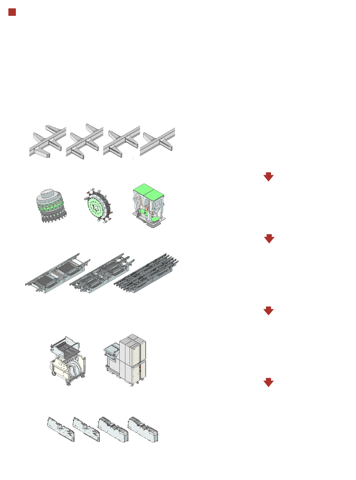
Modular Machine Concept
Step 1: Placement machine without heads and
component changeover tables
SIPLACE X4I
SIPLACE X4
SIPLACE X3
SIPLACE X2
Step 2: Select the placement heads
SpeedStar (C&P20)
MultiStar (CPP)
TwinStar (TH)
Step 3: Select the conveyor
Single conveyor
Flexible dual conveyor
Quad lane conveyor
Step 4: Select the component changeover table
and MTC
SIPLACE X component changeover table
MTC
Step 5: Select the feeder modules
X tape feeder modules
Label presenter
Reject conveyor
Waffle-pack tray holder
9
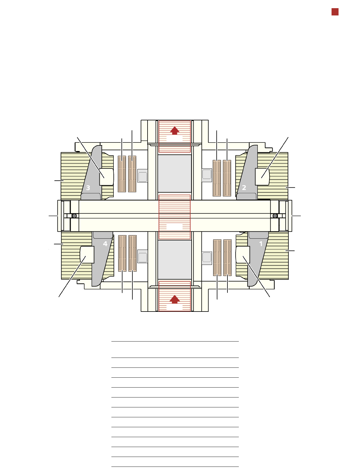
Modular Machine Concept
Example of the SIPLACE X4
NCH2
NCH1
NCH2
NCH1
C&P20/CPP/TH
X
MTC/X
C&P20/CPP/TH
NCH2
NCH1
NCH2
NCH1
PA1
PA2
C&P20/CPP/TH
MTC/X
X
C&P20/CPP/TH
33 Stationary IC camera, type 33
(with MultiStar and TwinStar only)
BZ Buffer zone
C&P20 SpeedStar
CPP MultiStar
MTC Matrix Tray Changer
NCH1 Nozzle changer, row 1
NCH2 Nozzle changer, row 2
OP Operator panel
PA1 Placement area 1
PA2 Placement area 2
TH TwinStar
X SIPLACE X component changeover table
OP
OP
BZ
BZ
BZ
PLEASE NOTE: The head configurations can be found in the
“Machine Performance” section from page 10.
33
33
33
33

10
Machine Performance
CPP_H = MultiStar CPP in high mounting position
CPP_L = MultiStar CPP in low mounting position
Types of placement head SIPLACE SpeedStar (C&P20)
SIPLACE MultiStar (CPP)
SIPLACE TwinStar (TH)
PLEASE NOTE The placement rate is affected by the different head combinations and
positions and by the conveyor configurations. Individual options and cus-
tomer-specific applications also affect the placement rate. On request,
SIPLACE can calculate the true output for your product on your machine
configuration.
IPC value [comp./h]
According to the vendor-neutral conditions of the IPC 9850 standard pub-
lished by the Association of Connecting Electronics Industries.
SIPLACE benchmark value [comp./h]
The SIPLACE benchmark value is measured during the machine accep-
tance tests. It corresponds to the conditions set out in the SIPLACE scope
of service and supply.
Theoretical maximum output value [comp./h]
The theoretical maximum output value is calculated from the most favor-
able conditions for each machine type and setting, and corresponds to
the theoretical conditions normally used in the industry.
SIPLACE X4I placement machine (I-placement mode)
For the definition of the placement performance values see the note above.
Number of gantries 4
Machine Placement area 1 Placement area 2 IPC value Benchmark value Theoretical value
X4I-A C&P20 / C&P20 C&P20 / C&P20 102,000 120,000 135,500
C&P20 / C&P20 CPP_L / CPP_L 91,500 107,000 123,750
CPP_L / CPP_L CPP_L / CPP_L 81,000 94,000 112,000
SIPLACE X4 placement system
For the definition of the placement performance values see the note above.
Number of gantries 4
Machine Placement area 1 Placement area 2 IPC value Benchmark value Theoretical value
X4-A C&P20 / C&P20 C&P20 / C&P20 82,000 90,000 124,000
C&P20 / C&P20 CPP_L / CPP_L 75,000 85,000 118,000
CPP_L / CPP_L CPP_L / CPP_L 68,000 80,000 112,000
X4-B C&P20 / C&P20 CPP_H / TH 61,900 68,600 93,000
CPP_L / CPP_L CPP_H / TH 54,900 63,600 87,000
X4-C C&P20 / C&P20 TH / TH 48,000 52,500 75,000
CPP_L / CPP_L TH / TH 41,000 47,500 69,000
X4-D CPP_H / TH TH / TH 27,900 31,100 44,000
X4-E TH / TH TH / TH 14,000 15,000 26,000