TS566R-UserGuide - 第29页
29 11 . I/O CONFIGURATION A ND END OF CYC LE FEEDBACK During a spray cycle, an open collector circuit closes and remains closed while the valve is dispensing . Pin 3 and 4 can be as feedback signal to synchronize with ot…

27
8. TROUBLESHOOTING
PROBLEM
POSSIBLE CAUSE
CORRECTION
Display does
not light up
• No power inputs
• Check power cord
connections
• Turn on power
System will not
actuate
• Supplied pressure
dropped below “Low
Pressure” setting
• Foot switch not plugged
in or improperly
plugged in
• Defective foot switch
• Broken wire or loose
connection inside unit
• Defective solenoid
• Defective PC board
• Increase supplied
pressure
• Check foot switch
connection
• Foot switch needs to be
repaired or replaced
• Unplug power cord and
disconnect air supply.
Remove cover and check
for broken wires or loose
connections
• Replace solenoid
• Replace PC board
System will not
pressurize
• Insufficient air pressure
• Air hoses not plugged
in
• Regulator defective
• Increase air supply
pressure
• Check connection
• Replace regulator
Inconsistent
spray coverage
• Air bubbles in material
• Activation time is too
low
• De-air material
• Increase activation time

28
9. MAINTENANCE
The controller is designed and built to be relatively maintenance free. To assure
trouble free operation, please follow below steps:
1. Make certain air supply is clean and dry.
2. Avoid connecting the unit to excessive moisture or solvent saturation
3. Avoid connecting air supply exceeding 100 psi (6.9 bars)
4. Use only Amyl Alcohol to clean outside surface of the main housing
5. Use only soft cloth to clean the display screen
10. LIMITED WARRANTY
OK International warrants this product to the original purchaser for a period of 2
years from date of purchase to be free from material and workmanship defects but
not normal wear-and-tear, abuse and faulty installation. Defective product or
subassembly and components under warranty will be repaired or replaced (at OK
International's option) free of charge. Customer with defective product under
warranty must contact the nearest OK International office or distributor to secure a
return authorization prior to shipping the product to the assigned OK International
authorized service center. For nearest OK International office or distributor contact
information, please visit www.techconsystems.com. OK International reserves the
right to make engineering product changes without notice.
All returns must be issued with a Returns Authorization number, prior to return.
Send warranty returns to:
Americas
OK International
10800 Valley View Street
Cypress, CA 90630
+1 714 230 2398
Europe
OK International
Eagle Close Chandler’s Ford Ind Est
Eastleigh, Hampshire
SO53 4NF
United Kingdom
+44 2380 489 100
Asia
Dover (Shenzhen) Industrial
Equipment Manufacturing Co., LTD.
4th Floor East, Electronic Building
Yanxiang Industrial Zone, High Tech Road
Guangmin New District
Shenzhen, P.R.C
+86 21 64952662
www.techconsystems.com
29
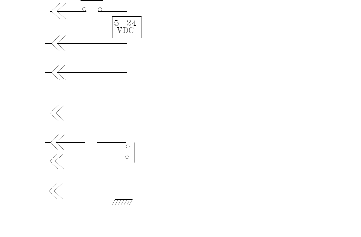
11. I/O CONFIGURATION AND END OF CYCLE FEEDBACK
During a spray cycle, an open collector circuit closes and remains closed while the
valve is dispensing. Pin 3 and 4 can be as feedback signal to synchronize with other
devices. Power from an external source is allowed to pass through the circuit to
operate a 5 to 24 VDC load. Power consumption must not exceed 250 mA. The
load could be a relay, solenoid, counter, LED, or any device that will operate within
a 5 to 24 VDC range and a maximum of 250 mA.
Note: During the spray cycle, pin 3 will be grounded. Please make sure the
external device (your machine that controls the controller) has the same ground
as the controller.
Pin 7, 8, and 9 = Available
Chassis Ground
To initiate a dispense cycle with
contact closure
When low pressure alarm is triggered, Pin 4 is grounded (-)
When low pressure alarm is turned off,
Pin 4 is not connected (opened)
End of Cycle Feedback
During dispensing cycle, Pin 3 is grounded (-)
End of dispensing cycle,
Pin 3 is not connected (opened)
To initiate a dispense cycle with voltage
Pin 1 (+)
Pin 2 (-)
Pin 3
Pin 4
Pin 5
Pin 6
Pin 5