IPC-CM-770D-1996 - 第101页
Januaw 1996 IPC-CM-770 Second level Top clamp plate heat sink or second level Clamping screw Edge connector Thermal grease I Buried via Spacar post IPC-I- Figure 19-4 Flexible Printed Board with Metal Support Plane core,…
IPC-CM-770
Januaty
1996
Power
plane
Metal
Supporting Plane
IPC-I-
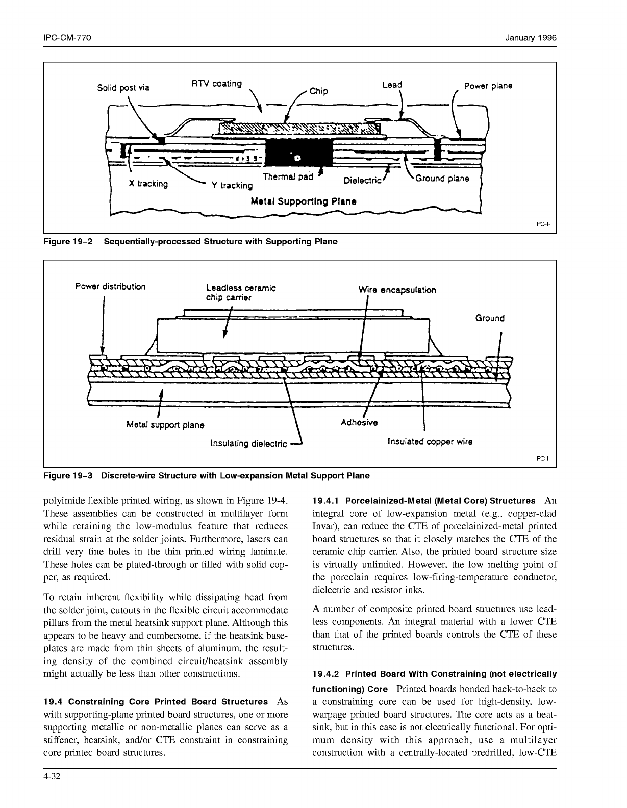
Figure 19-2 Sequentially-processed Structure with Supporting Plane
Power
distribution
Leadless
ceramic
Wire
encapsulation
Metal support plane
Insulating dielectric Insulated copper wire
IPC-I-
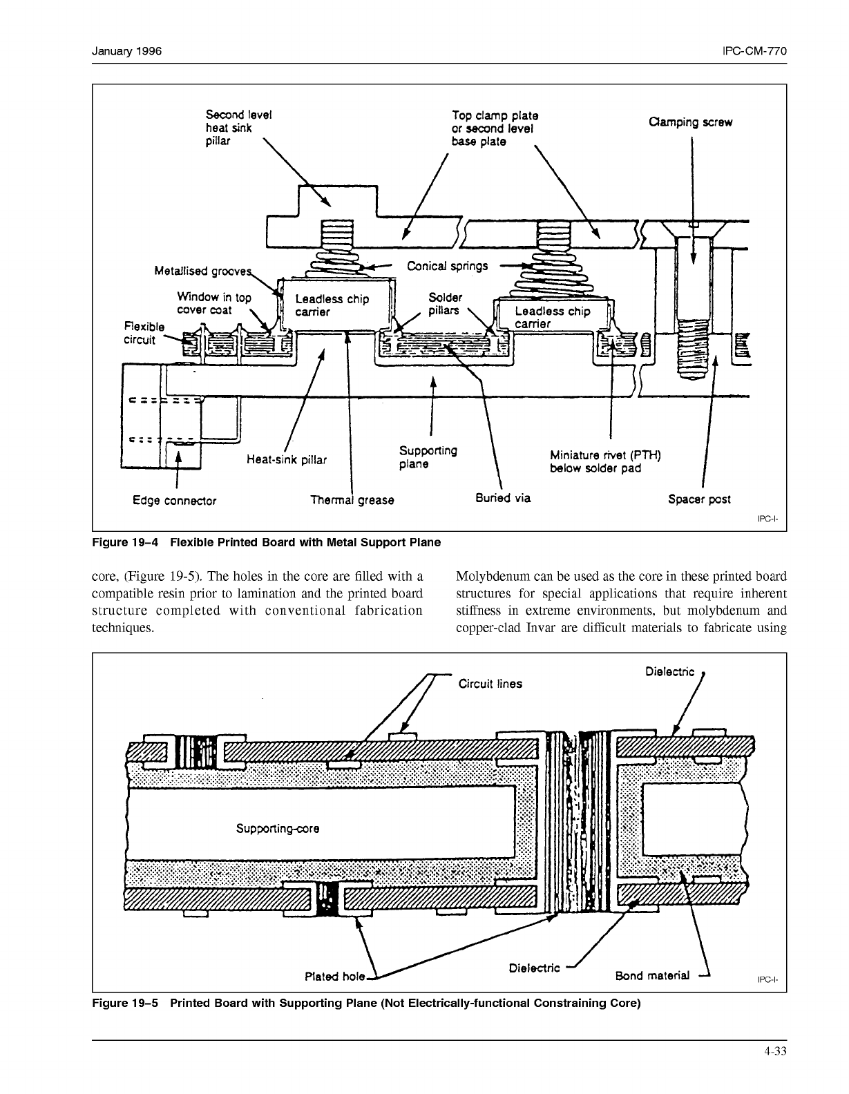
Figure 19-3 Discrete-wire Structure with Low-expansion Metal Support Plane
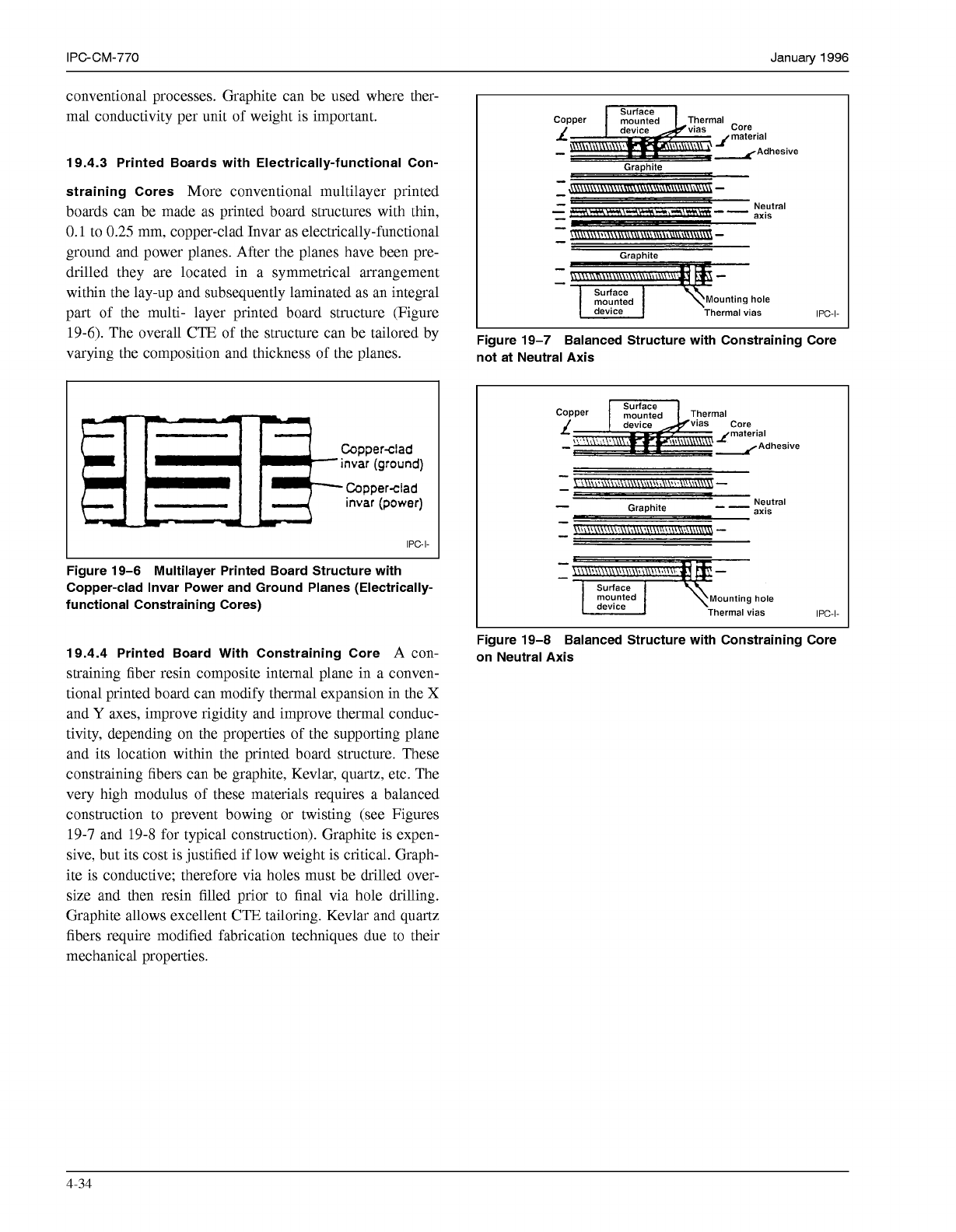
polyimide flexible printed wiring, as shown in Figure
19-4.
These assemblies can be constructed in multilayer form
while retaining the low-modulus feature that reduces
residual strain at the solder joints. Furthermore, lasers can
drill very fine holes in the thin printed wiring laminate.
These holes can be plated-through or filled with solid cop-
per, as required.
To retain inherent flexibility while dissipating head from
the solder joint, cutouts in the flexible circuit accommodate
pillars from the metal heatsink support plane. Although this
appears to be heavy and cumbersome, if the heatsink base-
plates are made from thin sheets of aluminum, the result-
ing density of the combined circuidheatsink assembly
might actually be less than other constructions.
19.4 Constraining Core Printed Board Structures
As
with supporting-plane printed board structures, one or more
supporting metallic or non-metallic planes can serve as a
stiffener, heatsink, and/or CTE constraint in constraining
core printed board structures.
19.4.1 Porcelainized-Metal (Metal Core) Structures
An
integral core of low-expansion metal (e.g., copper-clad
Invar), can reduce the CTE of porcelainized-metal printed
board structures
so
that it closely matches the CTE of the
ceramic chip carrier. Also, the printed board structure size
is virtually unlimited. However, the low melting point of
the porcelain requires low-firing-temperature conductor,
dielectric and resistor inks.
A number of composite printed board structures use lead-
less components. An integral material with a lower CTE
than that of the printed boards controls the CTE of these
structures.
19.4.2 Printed Board With Constraining (not electrically
functioning) Core
Printed boards bonded back-to-back to
a constraining core can be used for high-density, low-
warpage printed board structures. The core acts as a heat-
sink, but in this case is not electrically functional. For opti-
mum density with this approach, use a multilayer
construction with a centrally-located predrilled, low-CTE
4-32
COPYRIGHT Association Connecting Electronics Industries
Licensed by Information Handling Services
COPYRIGHT Association Connecting Electronics Industries
Licensed by Information Handling Services
Januaw
1996
IPC-CM-770
Second
level Top clamp plate
heat
sink
or
second
level
Clamping screw
Edge
connector
Thermal
grease
I
Buried via
Spacar
post
IPC-I-
Figure 19-4 Flexible Printed Board with Metal Support Plane
core, (Figure
19-5).
The holes in the core are filled with a Molybdenum can be used as the core in these printed board
compatible resin prior to lamination and the printed board structures for special applications that require inherent
structure completed with conventional fabrication stiffness in extreme environments, but molybdenum and
techniques.
copper-clad Invar are difficult materials to fabricate using
Dielectric
Circuit lines
/
Supportingare
\
/
m.
I"
IPC-I-
Figure 19-5 Printed Board with Supporting Plane (Not Electrically-functional Constraining Core)
4-33
COPYRIGHT Association Connecting Electronics Industries
Licensed by Information Handling Services
COPYRIGHT Association Connecting Electronics Industries
Licensed by Information Handling Services
IPC-CM-770
Januaty
1996
conventional processes. Graphite can be used where ther-
mal conductivity per unit of weight is important.
19.4.3 Printed Boards with Electrically-functional Con-
straining Cores
More conventional multilayer printed
boards can be made as printed board structures with thin,
0.1
to
0.25
mm, copper-clad Invar as electrically-functional
ground and power planes. After the planes have been pre-
drilled they are located in a symmetrical arrangement
within the lay-up and subsequently laminated as an integral
part of the multi- layer printed board structure (Figure
19-6).
The overall CTE of the structure can be tailored by
varying the composition and thickness of the planes.
IPC-I-
Figure 19-6 Multilayer Printed Board Structure with
Copper-clad Invar Power and Ground Planes (Electrically-
functional Constraining Cores)
19.4.4 Printed Board With Constraining Core
A con-
straining fiber resin composite internal plane in a conven-
tional printed board can modify thermal expansion in the
X
and
Y
axes, improve rigidity and improve thermal conduc-
tivity, depending on the properties of the supporting plane
and its location within the printed board structure. These
constraining fibers can be graphite, Kevlar, quartz, etc. The
very high modulus of these materials requires a balanced
construction to prevent bowing or twisting (see Figures
19-7
and
19-8
for typical construction). Graphite is expen-
sive, but its cost is justified if low weight is critical. Graph-
ite is conductive; therefore via holes must be drilled over-
size and then resin filled prior to final via hole drilling.
Graphite allows excellent CTE tailoring. Kevlar and quartz
fibers require modified fabrication techniques due to their
mechanical properties.
e
Graphite
-
I
",",Ed
1
\Mounting hole
Thermal vias
IPC-I-
Figure 19-7 Balanced Structure with Constraining Core
not at Neutral Axis
L
material
-
-Adhesive
giz:d \Mounting hole
Thermal vias
IPC-I-
Figure 19-8 Balanced Structure with Constraining Core
on Neutral Axis
4-34
COPYRIGHT Association Connecting Electronics Industries
Licensed by Information Handling Services
COPYRIGHT Association Connecting Electronics Industries
Licensed by Information Handling Services