IPC-CM-770D-1996 - 第102页
IPC-CM-770 Januaty 1996 conventional processes. Graphite can be used where ther- mal conductivity per unit of weight is important. 19.4.3 Printed Boards with Electrically-functional Con- straining Cores More conventional…
Januaw
1996
IPC-CM-770
Second
level Top clamp plate
heat
sink
or
second
level
Clamping screw
Edge
connector
Thermal
grease
I
Buried via
Spacar
post
IPC-I-
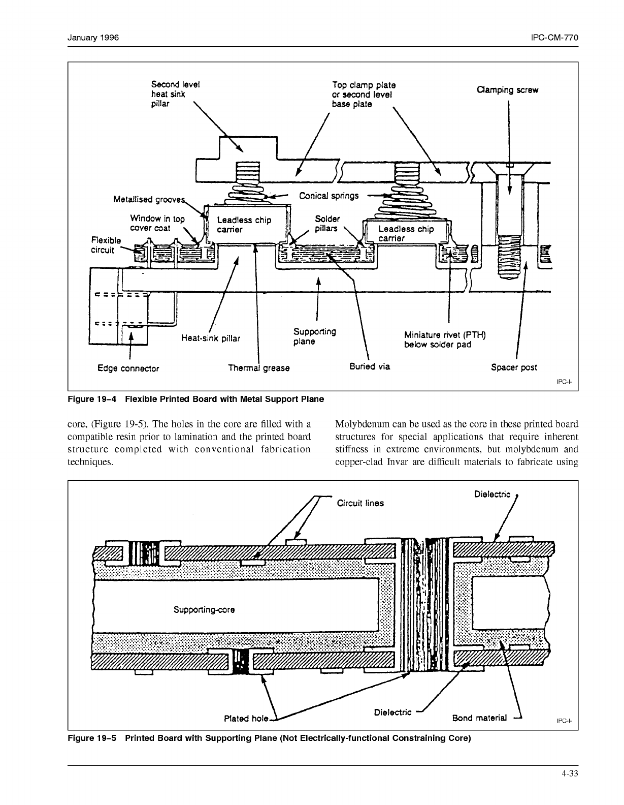
Figure 19-4 Flexible Printed Board with Metal Support Plane
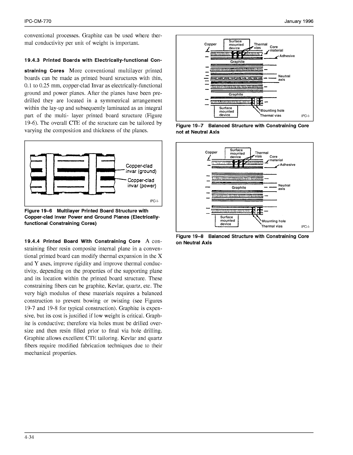
core, (Figure
19-5).
The holes in the core are filled with a Molybdenum can be used as the core in these printed board
compatible resin prior to lamination and the printed board structures for special applications that require inherent
structure completed with conventional fabrication stiffness in extreme environments, but molybdenum and
techniques.
copper-clad Invar are difficult materials to fabricate using
Dielectric
Circuit lines
/
Supportingare
\
/
m.
I"
IPC-I-
Figure 19-5 Printed Board with Supporting Plane (Not Electrically-functional Constraining Core)
4-33
COPYRIGHT Association Connecting Electronics Industries
Licensed by Information Handling Services
COPYRIGHT Association Connecting Electronics Industries
Licensed by Information Handling Services
IPC-CM-770
Januaty
1996
conventional processes. Graphite can be used where ther-
mal conductivity per unit of weight is important.
19.4.3 Printed Boards with Electrically-functional Con-
straining Cores
More conventional multilayer printed
boards can be made as printed board structures with thin,
0.1
to
0.25
mm, copper-clad Invar as electrically-functional
ground and power planes. After the planes have been pre-
drilled they are located in a symmetrical arrangement
within the lay-up and subsequently laminated as an integral
part of the multi- layer printed board structure (Figure
19-6).
The overall CTE of the structure can be tailored by
varying the composition and thickness of the planes.
IPC-I-
Figure 19-6 Multilayer Printed Board Structure with
Copper-clad Invar Power and Ground Planes (Electrically-
functional Constraining Cores)
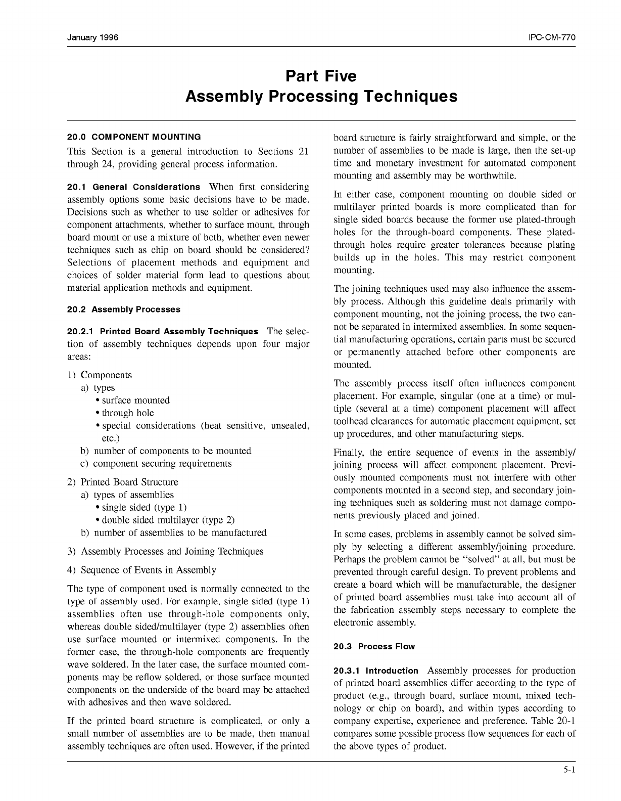
19.4.4 Printed Board With Constraining Core
A con-
straining fiber resin composite internal plane in a conven-
tional printed board can modify thermal expansion in the
X
and
Y
axes, improve rigidity and improve thermal conduc-
tivity, depending on the properties of the supporting plane
and its location within the printed board structure. These
constraining fibers can be graphite, Kevlar, quartz, etc. The
very high modulus of these materials requires a balanced
construction to prevent bowing or twisting (see Figures
19-7
and
19-8
for typical construction). Graphite is expen-
sive, but its cost is justified if low weight is critical. Graph-
ite is conductive; therefore via holes must be drilled over-
size and then resin filled prior to final via hole drilling.
Graphite allows excellent CTE tailoring. Kevlar and quartz
fibers require modified fabrication techniques due to their
mechanical properties.
e
Graphite
-
I
",",Ed
1
\Mounting hole
Thermal vias
IPC-I-
Figure 19-7 Balanced Structure with Constraining Core
not at Neutral Axis
L
material
-
-Adhesive
giz:d \Mounting hole
Thermal vias
IPC-I-
Figure 19-8 Balanced Structure with Constraining Core
on Neutral Axis
4-34
COPYRIGHT Association Connecting Electronics Industries
Licensed by Information Handling Services
COPYRIGHT Association Connecting Electronics Industries
Licensed by Information Handling Services
January
1996
IPC-CM-770
Part Five
Assembly Processing Techniques
20.0 COMPONENT MOUNTING
This Section is a general introduction to Sections 21
through 24, providing general process information.
20.1 General Considerations
When first considering
assembly options some basic decisions have to be made.
Decisions such as whether to use solder or adhesives for
component attachments, whether to surface mount, through
board mount or use a mixture of both, whether even newer
techniques such as chip on board should be considered?
Selections of placement methods and equipment and
choices of solder material form lead to questions about
material application methods and equipment.
20.2 Assembly Processes
20.2.1 Printed Board Assembly Techniques
The selec-
tion of assembly techniques depends upon four major
areas:
1)
Components
4
types
surface mounted
through hole
special considerations (heat sensitive, unsealed,
etc.)
b) number of components to be mounted
c) component securing requirements
2) Printed Board Structure
a) types of assemblies
single sided (type
1)
double sided multilayer (type 2)
b) number of assemblies to be manufactured
3)
Assembly Processes and Joining Techniques
4) Sequence of Events in Assembly
The type of component used is normally connected to the
type of assembly used. For example, single sided (type
1)
assemblies often use through-hole components only,
whereas double sided/multilayer (type 2) assemblies often
use surface mounted or intermixed components. In the
former case, the through-hole components are frequently
wave soldered. In the later case, the surface mounted com-
ponents may be reflow soldered, or those surface mounted
components on the underside of the board may be attached
with adhesives and then wave soldered.
If the printed board structure is complicated, or only a
small number of assemblies are to be made, then manual
assembly techniques are often used. However, if the printed
board structure is fairly straightforward and simple, or the
number of assemblies to be made is large, then the set-up
time and monetary investment for automated component
mounting and assembly may be worthwhile.
In either case, component mounting on double sided or
multilayer printed boards is more complicated than for
single sided boards because the former use plated-through
holes for the through-board components. These plated-
through holes require greater tolerances because plating
builds up in the holes. This may restrict component
mounting.
The joining techniques used may also influence the assem-
bly process. Although this guideline deals primarily with
component mounting, not the joining process, the two can-
not be separated in intermixed assemblies. In some sequen-
tial manufacturing operations, certain parts must be secured
or permanently attached before other components are
mounted.
The assembly process itself often influences component
placement. For example, singular (one at a time) or mul-
tiple (several at a time) component placement will affect
toolhead clearances for automatic placement equipment, set
up procedures, and other manufacturing steps.
Finally, the entire sequence of events in the assembly/
joining process will affect component placement. Previ-
ously mounted components must not interfere with other
components mounted in a second step, and secondary join-
ing techniques such as soldering must not damage compo-
nents previously placed and joined.
In some cases, problems in assembly cannot be solved sim-
ply by selecting a different assembly/joining procedure.
Perhaps the problem cannot be "solved" at all, but must be
prevented through careful design. To prevent problems and
create a board which will be manufacturable, the designer
of printed board assemblies must take into account all of
the fabrication assembly steps necessary to complete the
electronic assembly.
20.3 Process
Flow
20.3.1 Introduction
Assembly processes for production
of printed board assemblies differ according to the type of
product (e.g., through board, surface mount, mixed tech-
nology or chip on board), and within types according to
company expertise, experience and preference. Table 20-1
compares some possible process flow sequences for each of
the above types of product.
5-1
COPYRIGHT Association Connecting Electronics Industries
Licensed by Information Handling Services
COPYRIGHT Association Connecting Electronics Industries
Licensed by Information Handling Services