IPC-CM-770D-1996 - 第118页
IPC-CM-770 Januaty 1996 1 O0 70 30 20 :: 10 I O J v: I 1980 1985 19 'NON-IBM YEAR OTHER GOLD BALL BONDING 73% AI BAL L 3'1" ALUMINUM WEbGE BONDING 22% i% t 2 2% I IPC-1-00338 Figure 23-1 Chip Termination T…
January
1996
IPC-CM-770
both electrical and thermal conduction. Non-conductive
epoxies contain a basic resin and can contain additives to
promote thermal conduction.
Epoxies designed for die attach usually limit content of
volatile solvents. This reduces the amount of out gassing
and formation of voids. Inspection for voids is simply done
by using a clear glass die and viewing through the die after
adhesive cure. Advantages of using epoxies include:
Low temperature cure, however:
Cure temperature should not reach Tg of the board
Cure temperatures may age solder joints
Ease of processing with silk-screening or dispensing
equipment:
Appropriate adhesive viscosity is necessary for each
process
High Yield: Dependent on die yield and handling
Ease of removal for repair: Before encapsulation
Mechanical strength for ruggedness:
Can be verified with a die shear test
Epoxy bonding also dictates certain precautions, including:
A.
Heat control:
When thermocompression bonding is
used, a heated probe should be used, as the heat associated
with some types of thermocompression bonding will soften
the epoxy. (Does not apply when thermosonic bonding is
used.)
B. Precision tools:
If a vacuum-hold chuck is used to
mount the chips, check that each component forms a posi-
tive seal against the probe tip. Otherwise, epoxy might be
drawn to the top of the chip.
C. Chip processing:
If the gold is evaporated from sin-
tered chips that have gold backing in order to alloy the gold
with the silicon, the epoxy can pull away from the chip and
form a high resistance contact.
23.2.2 Eutectic Die Bonding
Eutectic die bonding
requires the back of the silicon die to be gold plated. At
sufficiently high temperatures the gold plating on the back
of the silicon chip melts with the gold plating on the die
site and forms a eutectic bond with the silicon. The silicon
device can withstand these high temperatures without
endangering performance or life expectancy. The die-attach
station should have the die attach area flooded with an inert
(forming gas or nitrogen) atmosphere.
23.2.3 Polyimide
Polyimides and silver-filled glass
adhesives have the ability to withstand higher temperatures
than epoxies. The polyimides used are thixotropic pastes
containing approximately
70%
silver powder in a polyim-
ide resin that has been dissolved in a high boiling tempera-
ture solvent. The main objection to their use is that they are
organic polymers and it is difficult to remove all of the
organics, which may outgas and cause chip degradation.
23.3 Wire Bonding Materials and Techniques
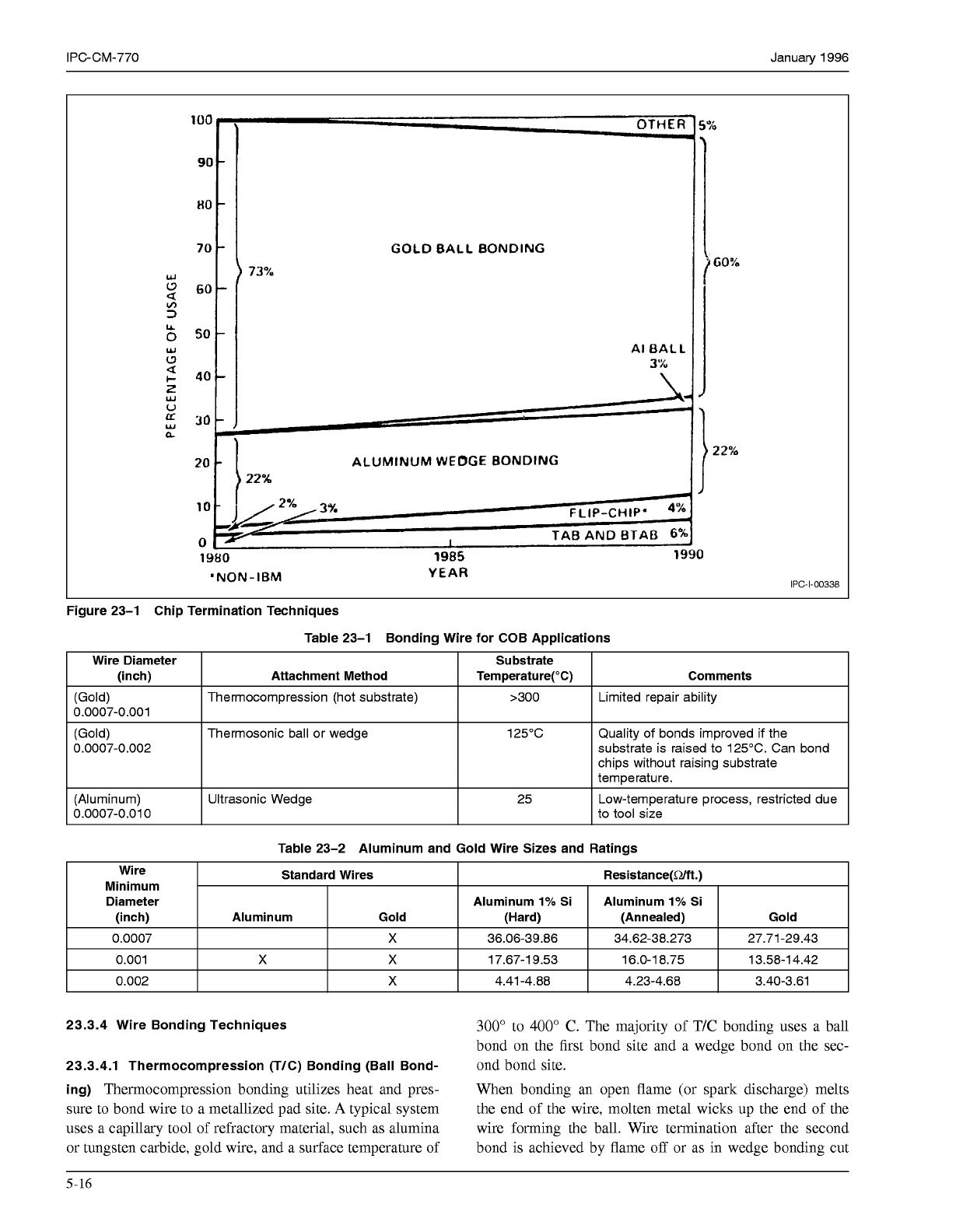
23.3.1 Bonding Wire
Both gold and aluminum wire are
used for chip on board (COB) applications (Figure 23-1).
Gold wires are typically alloyed with small amounts of
beryllium copper to control grain growth during bonding.
Aluminum wires are typically alloyed with
1%
silicon or
magnesium. For reference of standard wire see ASTM-F-
1.07.
Wire selection is dependent on the bonding techniques
(Table 23-1). The bonding technique determines the degree
of heat at the chip and board sites during bonding. The
amount of heat allowed and the wire termination selected
will limit the material choice and diameter of the wire.
Table 23-2 lists wire sizes and typical resistance values for
aluminum and gold wire. The current should be limited to
less than
0.5
amps for most applications.
A good gold wire bond should have a pull strength from
8
to
10
grams for 0.025 mm diameter wire. Aluminum wire
bonds usually achieve slightly less pull strength than gold.
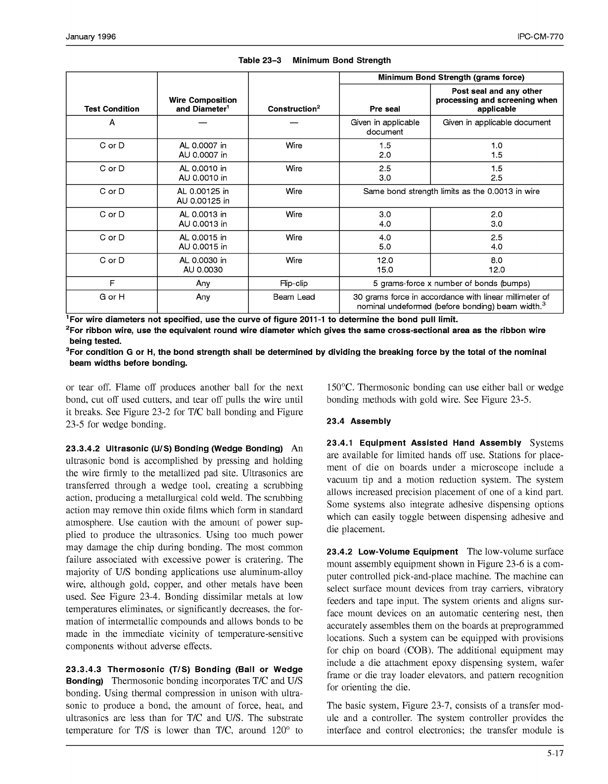
Table 23-3, Minimum Bond Strength, lists the wire diam-
eter and minimum acceptable pull strengths. Failure occur-
ring in the wire and not at the bond sites means the bonds
are stronger than the wire. This failure is preferred because
wire strength is usually under more control than the bond
sites.
23.3.2 Metallization
Metallization of the die and board
bond pads are very important to successful bonding and
reliability of the bonds. Verification of metallization purity
and thickness are critical. Limiting intermetallics between
wire and bond pad is important. The purity, additives, and
age of the bond wire are also important. The vendor can
supply all of this information. Bond integrity can be veri-
fied by bond pull and shear tests. Aging the wire bonds and
repeating pull and shear tests will give additional informa-
tion on reliability of the bond. Typical board plating for
gold wire bonding should be a minimum of 0.001mm of
99.99%
pure soft gold over
0.004
to 0.005mm of conven-
tional nickel. Aluminum wire bonding can be done reliably
with board plating that is similar to that for gold wire
bonding.
23.3.3 Printed Boards
Printed boards produced with
polymer conductive materials on low-temperature sub-
strates are now being made that are wire bondable. The
application of a plated-metal surface over the printed thick-
film polymer conductor pattern makes this possible. The
printed polymers currently being used for this type of
board construction are thermal-set, epoxy-silver conductors
and non-noble nickel polymers.
5-15
COPYRIGHT Association Connecting Electronics Industries
Licensed by Information Handling Services
COPYRIGHT Association Connecting Electronics Industries
Licensed by Information Handling Services
IPC-CM-770 Januaty 1996
1
O0
70
30
20
::
10
I
O
J
v:
I
1980
1985
19
'NON-IBM YEAR
OTHER
GOLD
BALL
BONDING
73%
AI
BAL
L
3'1"
ALUMINUM
WEbGE
BONDING
22%
i%
t
2
2%
I
IPC-1-00338
Figure 23-1 Chip Termination Techniques
Table 23-1 Bonding Wire for COB Applications
Wire Diameter Substrate
(inch)
Comments
Temperature("C)
Attachment Method
Thermocompression (hot substrate)
I
>300
I
Limited repair ability
0.0007-0.001
(Gold)
0.0007-0.002
Thermosonic ball or wedge 125°C Quality of bonds improved if the
substrate is raised to 125°C. Can bond
chips without raising substrate
temperature.
(Aluminum)
I
Ultrasonic Wedge
0.0007-0.010
I
25 Low-temperature process, restricted due
to tool size
Table 23-2 Aluminum and Gold Wire Sizes and Ratings
Wire
Minimum
Standard Wires
Aluminum
1%
Si Aluminum
1%
Si Diameter
Resistance(Rm.)
(inch)
Gold
(Annealed) (Hard)
Gold Aluminum
I
0.0007
I I
X
I
36.06-39.86
I
34.62-38.273
I
27.71-29.43
I
I
0.001
I
X
I
X
I
17.67-19.53
I
16.0-18.75
I
13.58-14.42
I
I
0.002
I I
X
I
4.41-4.88
I
4.23-4.68
I
3.40-3.61
I
23.3.4 Wire Bonding Techniques
300"
to
400"
C. The majority of T/C bonding uses a ball
bond on the first bond site and a wedge bond on the sec-
23.3.4.1 Thermocompression (T/C) Bonding (Ball Bond-
ond bond site.
ing)
Thermocompression bonding utilizes heat and pres- When bonding an open flame (or spark discharge) melts
sure to bond wire to a metallized pad site.
A
typical system the end of the wire, molten metal wicks up the end of the
uses a capillary tool of refractory material, such as alumina wire forming the ball. Wire termination after the second
or tungsten carbide, gold wire, and a surface temperature of bond is achieved by flame
off
or as in wedge bonding cut
5-16
COPYRIGHT Association Connecting Electronics Industries
Licensed by Information Handling Services
COPYRIGHT Association Connecting Electronics Industries
Licensed by Information Handling Services
January 1996 IPC-CM-770
Table 23-3 Minimum Bond Strength
Wire Composition rocessing and screening when
AU 0.0007 in
AU 0.0013 in
F
5
grams-force
x
number of bonds (bumps)
Flip-clip
Any
G
or
H
30 grams force in accordance with linear millimeter of Beam Lead
Any
nominal undeformed (before bonding) beam width.3
'For wire diameters not specified, use the curve of figure 2011-1 to determine the bond pull limit.
2For ribbon wire, use the equivalent round wire diameter which gives the same cross-sectional area as the ribbon wire
3For condition
G
or H, the bond strength shall be determined by dividing the breaking force by the total of the nominal
being tested.
beam widths before bonding.
or tear off. Flame off produces another ball for the next
bond, cut off used cutters, and tear off pulls the wire until
it breaks. See Figure 23-2 for T/C ball bonding and Figure
23-5 for wedge bonding.
23.3.4.2 Ultrasonic
(UIS)
Bonding (Wedge Bonding)
An
ultrasonic bond is accomplished by pressing and holding
the wire firmly to the metallized pad site. Ultrasonics are
transferred through a wedge tool, creating a scrubbing
action, producing a metallurgical cold weld. The scrubbing
action may remove thin oxide films which form in standard
atmosphere. Use caution with the amount of power sup-
plied to produce the ultrasonics. Using too much power
may damage the chip during bonding. The most common
failure associated with excessive power is cratering. The
majority of U/S bonding applications use aluminum-alloy
wire, although gold, copper, and other metals have been
used. See Figure 23-4. Bonding dissimilar metals at low
temperatures eliminates, or significantly decreases, the for-
mation of intermetallic compounds and allows bonds to be
made in the immediate vicinity of temperature-sensitive
components without adverse effects.
23.3.4.3 Thermosonic (TIS) Bonding (Ball or Wedge
Bonding)
Thermosonic bonding incorporates T/C and U/S
bonding. Using thermal compression in unison with ultra-
sonic to produce a bond, the amount of force, heat, and
ultrasonics are less than for T/C and U/S. The substrate
temperature for T/S is lower than T/C, around 120" to
150°C. Thermosonic bonding can use either ball or wedge
bonding methods with gold wire. See Figure 23-5.
23.4 Assembly
23.4.1 Equipment Assisted Hand Assembly
Systems
are available for limited hands off use. Stations for place-
ment of die on boards under a microscope include a
vacuum tip and a motion reduction system. The system
allows increased precision placement of one of a kind part.
Some systems also integrate adhesive dispensing options
which can easily toggle between dispensing adhesive and
die placement.
23.4.2 Low-Volume Equipment
The low-volume surface
mount assembly equipment shown in Figure 23-6 is a com-
puter controlled pick-and-place machine. The machine can
select surface mount devices from tray carriers, vibratory
feeders and tape input. The system orients and aligns sur-
face mount devices on an automatic centering nest, then
accurately assembles them on the boards at preprogrammed
locations. Such a system can be equipped with provisions
for chip on board (COB). The additional equipment may
include a die attachment epoxy dispensing system, wafer
frame or die tray loader elevators, and pattern recognition
for orienting the die.
The basic system, Figure 23-7, consists of a transfer mod-
ule and a controller. The system controller provides the
interface and control electronics; the transfer module is
5-17
COPYRIGHT Association Connecting Electronics Industries
Licensed by Information Handling Services
COPYRIGHT Association Connecting Electronics Industries
Licensed by Information Handling Services