IPC-CM-770D-1996 - 第139页
January 1996 IPC-CM-770 Table 26-2 Maximum Allowable Resistances and Discharge Times for Static Safe Operations Maximum Maximum Reading from Discharge Time Resistance Operator Through: Acceptable Tolerable* I I loo0 mego…
IPC-CM-770
Januaty
1996
Know the ESD caution symbols.
Bolt interconnecting wires to the mats to achieve good
electrical contact.
Use a spike-free and grounded soldering iron.
B.
Don’t:
Don’t allow anyone not grounded to touch ESD sensitive
components in the work area. To be grounded, they must
be standing on the conductive floor mat and must first
touch the conductive benchtop mat before touching the
components or printed circuit cards.
Don’t place ESD-sensitive components on ungrounded
work areas.
Don’t wear extremely thick-soled shoes (like wedgies) or
shoes with heavy plastic soles (like earthshoes). These
will act as insulators and will allow buildup of high static
charges on the operator.
Don’t touch the component by the pins or leads since the
most damage is done at these points by ESD. Handle the
components by their cap edges or body and the printed
circuit cards by their edges.
Don’t handle components or printed circuit cards during
transport from work station to work station. Components
or cards must not be directly handled by anyone not
grounded.
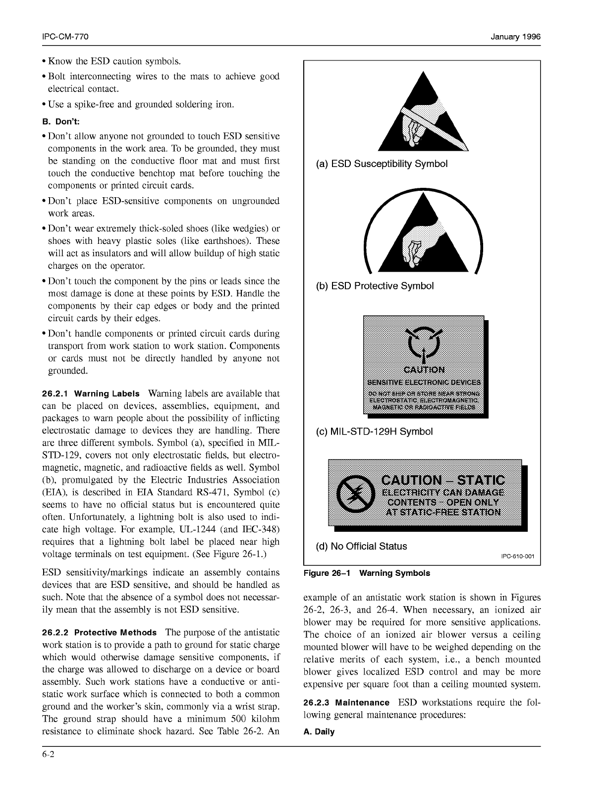
26.2.1 Warning Labels
Warning labels are available that
can be placed on devices, assemblies, equipment, and
packages to warn people about the possibility of inflicting
electrostatic damage to devices they are handling. There
are three different symbols. Symbol (a), specified in MIL-
STD-129, covers not only electrostatic fields, but electro-
magnetic, magnetic, and radioactive fields as well. Symbol
(b), promulgated by the Electric Industries Association
(EIA), is described in EIA Standard RS-471, Symbol (c)
seems to have no official status but is encountered quite
often. Unfortunately, a lightning bolt is also used to indi-
cate high voltage. For example, UL-1244 (and IEC-348)
requires that a lightning bolt label be placed near high
voltage terminals on test equipment. (See Figure 26-1.)
ESD sensitivity/markings indicate an assembly contains
devices that are ESD sensitive, and should be handled as
such. Note that the absence of a symbol does not necessar-
ily mean that the assembly is not ESD sensitive.
26.2.2 Protective Methods
The purpose of the antistatic
work station is to provide a path to ground for static charge
which would otherwise damage sensitive components,
if
the charge was allowed to discharge on a device or board
assembly. Such work stations have a conductive or anti-
static work surface which is connected to both a common
ground and the worker’s skin, commonly via a wrist strap.
The ground strap should have a minimum
500
kilohm
resistance to eliminate shock hazard. See Table 26-2. An
(a) ESD Susceptibility Symbol
(b) ESD Protective Symbol
(c) MIL-STD-129H Symbol
(d)
No
Official Status
IPC-610-001
Figure 26-1 Warning Symbols
example of an antistatic work station is shown in Figures
26-2, 26-3, and 26-4. When necessary, an ionized air
blower may be required for more sensitive applications.
The choice of an ionized air blower versus a ceiling
mounted blower will have to be weighed depending on the
relative merits of each system, i.e., a bench mounted
blower gives localized ESD control and may be more
expensive per square foot than a ceiling mounted system.
26.2.3 Maintenance
ESD workstations require the fol-
lowing general maintenance procedures:
A.
Daily
6-2
COPYRIGHT Association Connecting Electronics Industries
Licensed by Information Handling Services
COPYRIGHT Association Connecting Electronics Industries
Licensed by Information Handling Services
January
1996
IPC-CM-770
Table 26-2 Maximum Allowable Resistances and
Discharge Times for Static Safe Operations
Maximum Maximum
Reading from
Discharge Time Resistance Operator Through:
Acceptable
Tolerable*
I I
loo0
megohms
I
Floor mat
to ground
Less than
1
sec.
I
loo0
megohms
I
Less than
1
sec.
to ground
I
Wrist
strap
I
loo
megohms
I
Less than
0.1
sec
to ground
*Minimum resistance to ground for each
is
500
kilohms.
Perform visual inspection of grounding wires and termi-
nals on floormat, benchtop, and grounding receptacle to
insure that proper electrical connections exist.
Clear workstation of static generators, plastic, foams,
cardboard, etc.
Clean benchtop mats with a soft cloth or paper towel
dampened with a mild solution of detergent and water.
B. Weekly
Damp mop floormats (according to the manufacturer’s
recommendation) to remove any accumulated dirt layer
which causes high resistivity.
26.2.4 Handling
All components and/or assemblies des-
ignated as ESD sensitive should be removed from their
protective packaging (anti-static bags, conductive contain-
ers) only at a static safe work station. The following pro-
cedure must be followed before ESD sensitive items are
removed from their protective packaging:
Clear work station of static generators, polyethylene,
vinyls, foam, notebooks, document holders, etc.
Verify grounding wires and connect wrist straps.
Discharge personal static prior to handling devices/
assemblies.
Place protective container on work surface, remove
device/assembly.
After removal of device/assembly from protective packing
and during inspection, testing or assembly, handling should
be as follows (also see Figure
26-6
for proper handling
procedures):
Devices should not be handled by the leads. Avoid touch-
ing leads, circuits, or contacts on assemblies and printed
circuit board assemblies which contain sensitive devices.
Avoid sliding movements of devices over work surface at
any time.
Do not allow devices to contact ordinary plastics or tex-
tiles. Avoid wearing nylon or synthetic type gowns; cot-
ton or a cotton blend is preferred. Short sleeves are also
preferred.
Do not probe or test static sensitive devices with a volt-
ohm meter.
When work is complete, replace device/assembly in con-
ductive bag or container and apply cautionary labels.
26.3 Storage
The preservation of solderability and the
protection of parts and assemblies from handling and ESD
damage should be a vital control aspect of the manufactur-
ing process of printed board assemblies.
Printed boards should be individually wrapped before ship-
ping or transportation to the destination where they will be
received and assembled.
Boards should not be allowed to touch or rub against one
another.
26.3.1 Bags
One of the most common forms of protec-
tion for bare boards is polyethylene bags. Heat sealed, zip-
locked or folded over and taped.
Ensure the boards are thoroughly cleaned before being
packaged and that the atmosphere in which the boards are
packed is reasonably dry. Sealing moisture or a contami-
nated environment within a bag, which is worse, can affect
the solderability and moisture content of the boards. This is
especially true during summer months with high humidity.
Laminated-welded bags (or hot sealed bags) provide the
best protection for long term storage and the boards stored
this way have better solderability than boards in other
packaging.
Printed boards, components and hardware are frequently
replaced in their original containers and put on a shelf until
they are required. Some consideration should be given at
this point to the packing material. If the manufacturer did
not provide a protective material, it is advisable to repack-
age in an approved container.
Parts should not be stored in open containers subject to the
environment, dust and air pollutants that may cause the
parts to oxidize.
Inventory control practice should carefully handle the parts
with a “first in-first out” policy.
Components and boards should not be left exposed over-
night or weekends to accumulate dust and debris from the
atmosphere.
Printed boards distributed to the manual assembly line
should either be racked with spaces between, or stacked
with interleaved paper between, particularly if they are
two-sided boards.
26.3.2 Materials
Care should be exercised to assure that
packaging materials do not contain additives or surface
treatment that will deteriorate solderability or degrade the
insulation properties of components, boards or assemblies.
26.3.3 Racks and Carriers
There are a number of racks
and carriers for assembled boards if they must be stored
6-3
COPYRIGHT Association Connecting Electronics Industries
Licensed by Information Handling Services
COPYRIGHT Association Connecting Electronics Industries
Licensed by Information Handling Services
IPC-CM-770
Januaty
1996
-
-
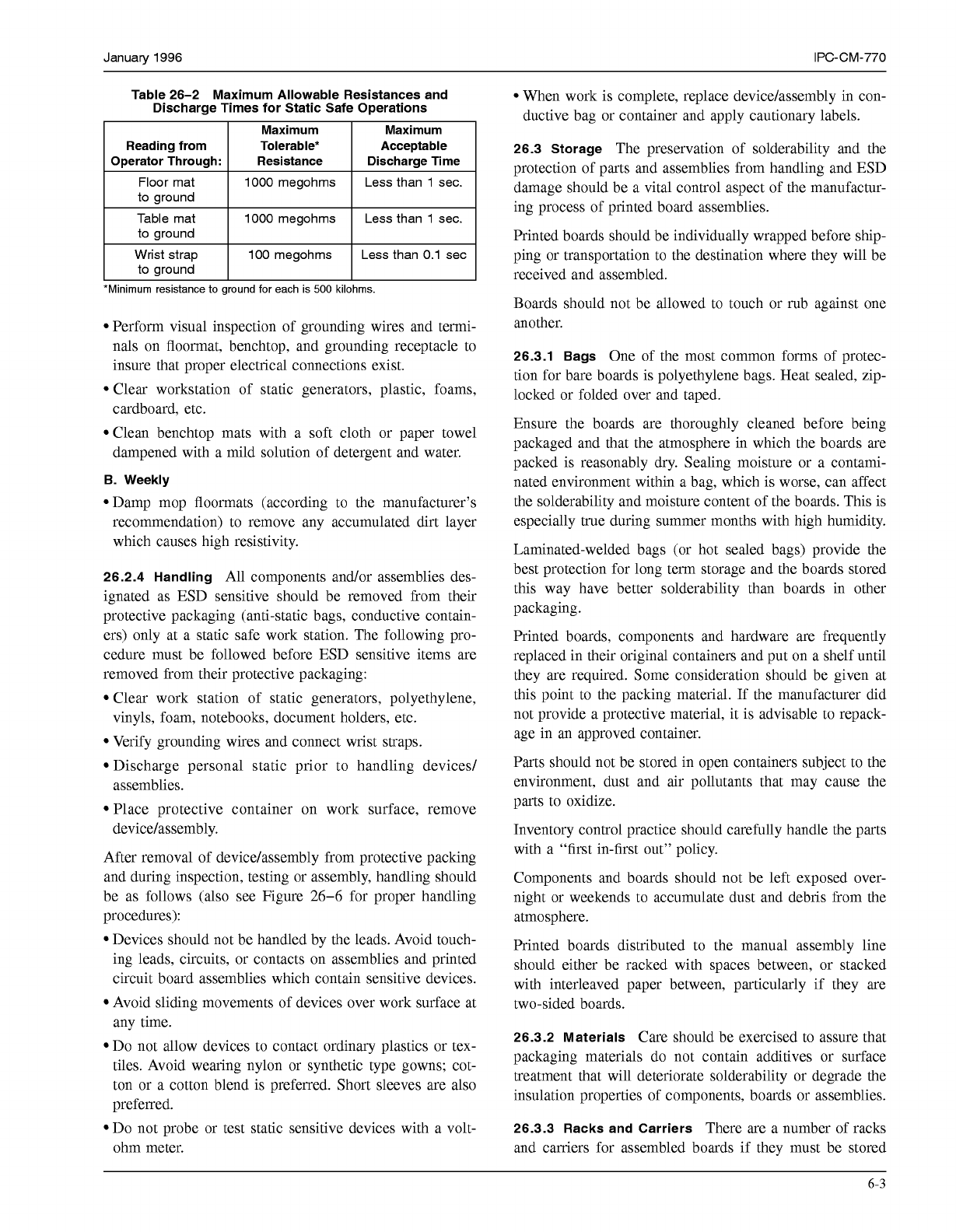
Figure 26-2 Schematic
of
a Typical Grounded Work Station
Component
Function
or
ccaductive
flooring
and
Floormat
S.NOS
as
IWK
drain
br
p.-
appcosch~ng
the
work
&tion.
Drain6 away charges yeneraled
by
walking
across
floors
(or conductive
Benchtop
mat Pr0nd.s
a
auk-irao
work
ruriwx
Salic
Ch.rgos ara
dra~fmd
away from any aIec~rontc components
or
prlnled clrcull
urds
rosllng
on
th.
suriua
of
th.
mal.
Ground
cord
Prwldes
m
olutrical
connullon
be1ww1-1
lunchlop
nut
and
I(oorrne1
and
ptnr
lhose
Iwo
surfaces
lo
an sanh groutrd
bench
top)
thmm
I
MO
I.Sl*OT
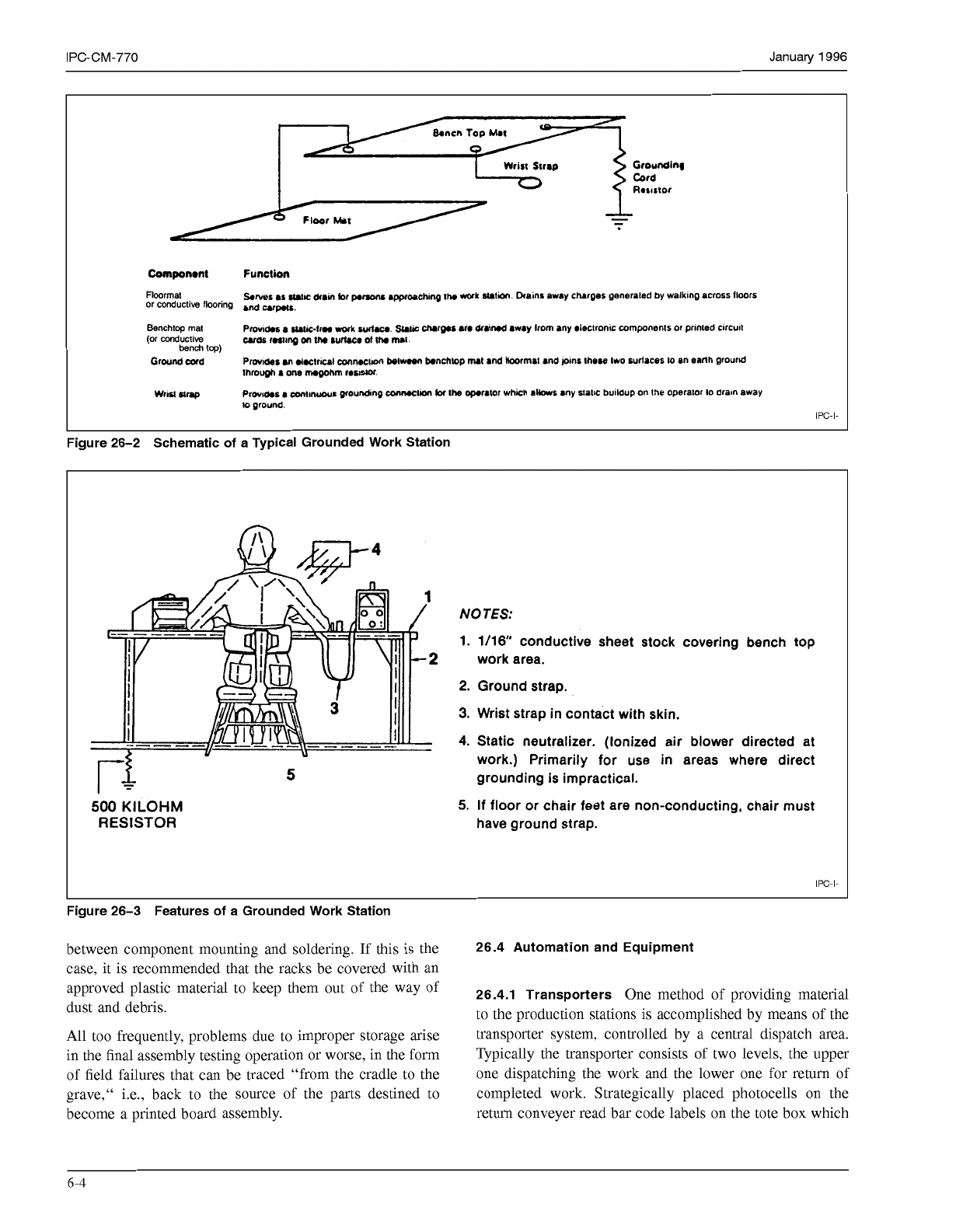
500
KILOHM
RESISTOR
5
NO
TES:
1. 1/16
conductive sheet stock covering bench
top
work area.
2.
Ground strap.
3.
Wrist strap in contact with skin.
4.
Static neutralizer. (Ionized air blower directed at
work.) Primarily
for
use in areas where direct
grounding
is
impractical.
5.
If
floor
or
chair feet are non-conducting, chair must
have ground strap.
IPC-I-
Figure 26-3 Features
of
a Grounded Work Station
between component mounting and soldering. If this is the
26.4 Automation and Equipment
case, it is recommended that the racks be covered with an
dust and debris.
to the production stations is accomplished by means of the
All too frequently, problems due to improper storage arise transporter system, controlled by a central dispatch area.
in the final assembly testing operation or worse, in the form Typically the transporter consists of two levels, the upper
of field failures that can be traced "from the cradle to the one dispatching the work and the lower one for return of
grave," i.e., back to the source of the parts destined to completed work. Strategically placed photocells on the
become a printed board assembly. return conveyer read bar code labels on the tote box which
approved plastic
to
keep
them
Out Of
the
way
Of
26.4.1 Transporters
One method of providing material
6-4
COPYRIGHT Association Connecting Electronics Industries
Licensed by Information Handling Services
COPYRIGHT Association Connecting Electronics Industries
Licensed by Information Handling Services