IPC-CM-770D-1996 - 第147页
January 1996 IPC-CM-770 Table 27-2 Solder Bath Contamination Limits Solder Joint Characteristic Guidelines 1/ The tin content of the solder bath shall be within 1: of the limits of 00-5-571 for the solder specified and t…
IPC-CM-770 Januaty 1996
no deleterious impact on reliability and do not need to be
removed from the assembly with a post solder defluxing
operation.
Other no clean fluxes, no residue, are formulated with no
rosin and utilize a mixture of one or more weak dicarbox-
cylic acids and wetting agents to provide the activation
needed to enhance soldering. These fluxes leave little or no
residue and do not need to be removed from the assembly
with a post solder defluxing operation.
An inert gas atmosphere, such as nitrogen, is often used to
enhance the soldering process when using these more
benign fluxes.
27.3.2 Solders
Solders are generally metal alloys with
melting points in the range -150°C to -400°C. Below this
temperature range, alloys are commonly called fusible
alloys: above this they are called brazes. Tin-lead alloys are
most common, although more complex compositions had
been developed for special applications.
For electrical soldering, alloys near the eutectic composi-
tion (63% tin 37% lead) have the required combination of
properties. Although compositions either side of the eutec-
tic have higher liquidus (completely melted) temperatures
desirable for higher ambient temperature applications,
remember that the initial melting point (at which solder
softens) is 183"C, the same for all tin-lead alloys with
compositions between 20% and
98%
tin.
The range of properties of tin-lead alloys can be varied by
adding other metals such as bismuth or indium to lower the
melting point, or antimony, silver, etc. to increase hardness
and fatigue resistance. Alloys containing less than
10%
tin
are used for applications involving temperatures below
-40°C.
27.3.2.1 Solder Alloy Selection
Selecting a solder alloy
for a particular assembly depends on the expected operat-
ing conditions and on the types of components used. For
example, the mechanical and fatigue properties of solder
may be more important for surface mounted components
than through hole components.
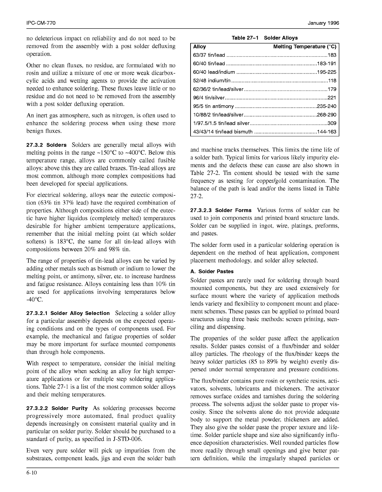
With respect to temperature, consider the initial melting
point of the alloy when seeking an alloy for high temper-
ature applications or for multiple step soldering applica-
tions. Table 27-1 is a list of the most common solder alloys
and their melting temperatures.
27.3.2.2 Solder Purity
As soldering processes become
progressively more automated, final product quality
depends increasingly on consistent material quality and in
particular on solder purity. Solder should be purchased to a
standard of purity, as specified in J-STD-006.
Even very pure solder will pick up impurities from the
substrates, component leads, jigs and even the solder bath
Table 27-1 Solder Alloys
Alloy Melting Temperature
("C)
63/37 tin/lead
.....................................................................
183
60/40 tin/lead
..............................................................
183-1 91
60/40 lead/indium
.......................................................
195-225
52/48 indiumkin
..................................................................
11 8
62/36/2 tin/lead/silver
.........................................................
179
96/4 tin/silver
......................................................................
221
95/5 tin antimony
........................................................
235-240
10/88/2 tin/lead/silver
..................................................
268-290
1/97.5/1.5 tin/lead silver
.....................................................
309
43/43/14 tin/lead bismuth
...........................................
144-1 63
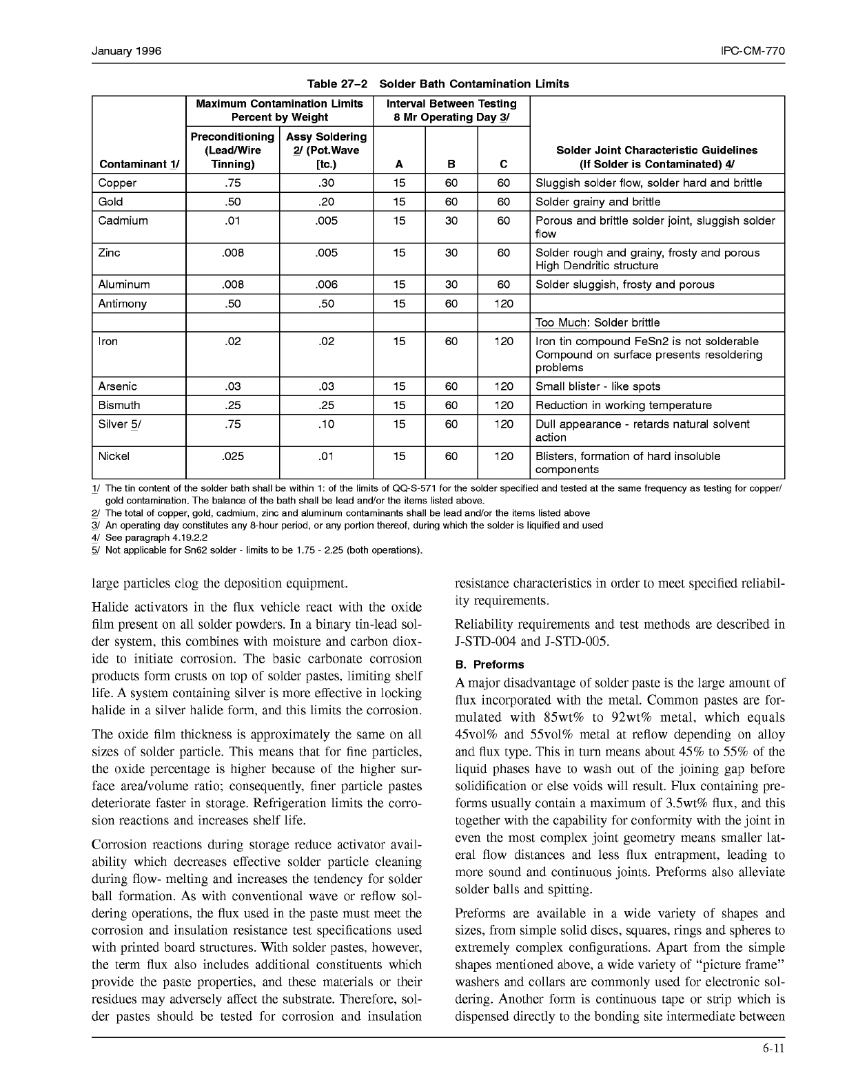
and machine tracks themselves. This limits the time life of
a solder bath. Typical limits for various likely impurity ele-
ments and the defects these can cause are also shown in
Table 27-2. Tin content should be tested with the same
frequency as testing for copper/gold contamination. The
balance of the path is lead and/or the items listed in Table
27-2.
27.3.2.3 Solder Forms
Various forms of solder can be
used to join components and printed board structure lands.
Solder can be supplied in ingot, wire, platings, preforms,
and pastes.
The solder form used in a particular soldering operation is
dependent on the method of heat application, component
placement methodology, and solder alloy selected.
A. Solder Pastes
Solder pastes are rarely used for soldering through board
mounted components, but they are used extensively for
surface mount where the variety of application methods
lends variety and flexibility to component mount and place-
ment schemes. These pastes can be applied to printed board
structures using three basic methods: screen printing, sten-
ciling and dispensing.
The properties of the solder paste affect the application
results. Solder pastes consist of a fluhinder and solder
alloy particles. The rheology of the fluxhinder keeps the
heavy solder particles
(85
to
89%
by weight) evenly dis-
persed under normal temperature and pressure conditions.
The fluhinder contains pure rosin or synthetic resins, acti-
vators, solvents, lubricants and thickeners. The activator
removes surface oxides and tarnishes during the soldering
process. The solvents adjust the solder paste to proper vis-
cosity. Since the solvents alone do not provide adequate
body to support the metal powder, thickeners are added.
They also give the solder paste the proper texture and life-
time. Solder particle shape and size also significantly influ-
ence deposition characteristics. Well rounded particles flow
more readily through small openings and give better pat-
tem definition, while the irregularly shaped particles or
6-10
COPYRIGHT Association Connecting Electronics Industries
Licensed by Information Handling Services
COPYRIGHT Association Connecting Electronics Industries
Licensed by Information Handling Services
January
1996
IPC-CM-770
Table
27-2
Solder Bath Contamination Limits
Solder Joint Characteristic Guidelines
1/ The tin content of the solder bath shall be within 1: of the limits of 00-5-571 for the solder specified and tested at the same frequency as testing for copper/
2/ The total of copper, gold, cadmium, zinc and aluminum contaminants shall be lead and/or the items listed above
3/
An operating day constitutes any 8-hour period, or any portion thereof, during which the solder is liquified and used
gold contamination. The balance of the bath shall be lead and/or the items listed above.
&/
See paragraph 4.19.2.2
5/ Not applicable for Sn62 solder
-
limits to be 1.75
-
2.25 (both operations).
large particles clog the deposition equipment.
Halide activators in the flux vehicle react with the oxide
film present on all solder powders. In a binary tin-lead sol-
der system, this combines with moisture and carbon diox-
ide to initiate corrosion. The basic carbonate corrosion
products form crusts on top of solder pastes, limiting shelf
life. A system containing silver is more effective in locking
halide in a silver halide form, and this limits the corrosion.
The oxide film thickness is approximately the same on all
sizes of solder particle. This means that for fine particles,
the oxide percentage is higher because of the higher sur-
face aredvolume ratio; consequently, finer particle pastes
deteriorate faster in storage. Refrigeration limits the corro-
sion reactions and increases shelf life.
Corrosion reactions during storage reduce activator avail-
ability which decreases effective solder particle cleaning
during flow- melting and increases the tendency for solder
ball formation. As with conventional wave or reflow sol-
dering operations, the flux used in the paste must meet the
corrosion and insulation resistance test specifications used
with printed board structures. With solder pastes, however,
the term flux also includes additional constituents which
provide the paste properties, and these materials or their
residues may adversely affect the substrate. Therefore, sol-
der pastes should be tested for corrosion and insulation
resistance characteristics in order to meet specified reliabil-
ity requirements.
Reliability requirements and test methods are described in
J-STD-O04 and J-STD-005.
B. Preforms
A major disadvantage of solder paste is the large amount of
flux incorporated with the metal. Common pastes are for-
mulated with 85wt% to 92wt% metal, which equals
45~01% and 55~01% metal at reflow depending on alloy
and flux type. This in turn means about 45% to
55%
of the
liquid phases have to wash out of the joining gap before
solidification or else voids will result. Flux containing pre-
forms usually contain a maximum of 3.5wt% flux, and this
together with the capability for conformity with the joint in
even the most complex joint geometry means smaller lat-
eral flow distances and less flux entrapment, leading to
more sound and continuous joints. Preforms also alleviate
solder balls and spitting.
Preforms are available in a wide variety of shapes and
sizes, from simple solid discs, squares, rings and spheres to
extremely complex configurations. Apart from the simple
shapes mentioned above, a wide variety of “picture frame”
washers and collars are commonly used for electronic sol-
dering. Another form is continuous tape or strip which is
dispensed directly to the bonding site intermediate between
6-11
COPYRIGHT Association Connecting Electronics Industries
Licensed by Information Handling Services
COPYRIGHT Association Connecting Electronics Industries
Licensed by Information Handling Services
IPC-CM-770
Januaty
1996
strip and individual preforms are chains where each unit is
broken off as it is dispensed.
The assembly sequence using preforms can be very simple.
The placement method of the preforms between component
parts or component and substrate is often the single most
unique feature of a preform process. The preform materials
have to be fixed or located between the components of the
joint with sufficient accuracy to insure that on melting the
metal contacts both parts of the joint
so
that they wet, and
surface tension forces can act to draw them into perfect
alignment. After this, the only remaining stage is to reflow
melt the preform. Solder preforms may be located by plac-
ing them over a lead or projection in the chip carrier, or by
positioning them in a groove or notch on the substrate.
Another alternative is to use auxiliary jigs and plates to
immobilize preforms until the reflow operation. Regardless
of the placement method, the preforms may be handled
through simple manual transfer, vibrator units, tumble
plates, or two part alignment plates.
In general, flux cannot be used to tack preforms in place
since the flux layer melts before the metal, allowing the
solid preform to float and move over the substrate. The
same applies to using partial flux reflow from flux filled
and flux coated preforms.
Metal coated preforms, however, can be affixed by partial
reflow, provided there is sufficient difference in melting
point between the cladding alloy and the core. Reflow of
the cladding layer can be used to attach the preform to one
side of the joint, which can then be fully assembled and
reflowed at the higher temperature to complete the bonding
operation.
The vapor-phase process is particularly suited for this if
alloy melting points allow the use of different reflow fluids.
A reflow fluid with a boiling point of 215°C would create
a molten surface zone to attach the preform. Subsequent
use of a reflow fluid with a boiling point of 250°C would
reflow the whole composite assembly.
27.4 Component Retention
Component retention is
described in detail in section 21.4.
27.5 Machine Soldering Processes
Soldering is defined
as a joining process with the use of heat (below 400°C) and
a non-ferrous filler metal that has a melting temperature
below that of the base metals to be joined. Soldering is a
practical technique for producing mechanically sound and
electrically reliable interconnections. Different soldering
processes exist, suited for a variety of electronics assembly
applications and technologies. The following sections
describe the specific details of the most common processes
used for mass production soldering of electronics
assemblies.
27.5.1 Wave Soldering
The large percentage of through-
hole board mounted components are mass wave soldered.
Small surface mount components such as passive chip
capacitors and resistors as well as SOTS (small outline tran-
sistors), bonded to the bottom side of the board with an
adhesive are also wave soldered extensively.
Wave soldering involves the following sequence of
operations:
Fluxing
Preheating
Soldering
27.5.1.1 Fluxing
A flux is applied to the bottom surface
of the electronics assembly as the first step after loading it
into the conveyor system of the wave soldering machine.
The flux also coats the component leads and some flux
enters the plated holes in the board. Flux is required to
remove oxides from the metallic surfaces to be soldered.
Flux also promotes solder wetting, helps the solder to rise
in plated holes, leaves solder joints with a smooth and
oxide-free surface and can prevent solder balls, solder sliv-
ers and webbing from remaining on the board surface after
soldering.
One commonly used method for applying a flux in a wave
soldering machine is foam fluxing. Other methods are
spray fluxing, wave fluxing and brush fluxing. Fluxers are
fabricated from materials which are compatible with the
chemical nature of fluxes. For rosin fluxes, the fluxer is
often fabricated from stainless steel or polyvinylchlo-
ride(PVC), a chemically resistant plastic material. For
water soluble acid fluxes which are more corrosive, the
units are either made of PVC or titanium.
A.
Foam Fluxing
Many wave soldering systems utilize foam fluxers. This is
the simplest method for applying flux. The foam is gener-
ated by feeding low-pressure compressed air into a porous
diffuser stone or a porous plastic diffuser or filter tube
which is immersed into the liquid flux in the fluxer bath.
The pores in the diffuser tube range from
50-60
micron
pore size for regular fluxes down to
10
microns for low
solids fluxes. The fine foam bubbles of flux are generated
by the air coming out of the pores. The flux rises in a cen-
trally mounted chimney nozzle which guides the foam
upward till it overflows the top edge of the chimney. As the
assembly is conveyed over the foam fluxer chimney, the
bottom of the board touches the foam head and becomes
coated with flux. A short distance after the exit end of the
fluxer an air knife is usually used, made from a tube with
small diameter holes drilled in a row along its length. Low
pressure air is directed upward at a slight angle toward the
entry end of the machine to remove excess flux and drip-
pings without disturbing the components. A well designed
6-12
COPYRIGHT Association Connecting Electronics Industries
Licensed by Information Handling Services
COPYRIGHT Association Connecting Electronics Industries
Licensed by Information Handling Services