IPC-CM-770D-1996 - 第163页
January 1996 IPC-CM-770 solder joint. The mass of the solder joint and the cooling sink characteristics of the base material, coupled with inter- nally connected thermally conductive loads, can signifi- cantly affect the…
IPC-CM-770
Januaty
1996
While no known universal component R&R equipment (for
all types of printed boards exist, structures and all types of
components) the general R&R controlled process equip-
ment requirements include the following:
A. Controlled application of heat to melt the solder joints
of the component in question without causing thermal dam-
age to the base material, or to any component, or the remelt
of any adjacent solder joints.
B.
Controlled removal of the component after sensing sol-
der melt, to prevent delamination of the lands or destruc-
tion of the plated through holes on the printed board struc-
ture.
C. Preparation of the printed board lands, removal of
residual solder in plated through holes, and pre-tinning of
the component leads or lead surfaces in preparation of
component replacement and resoldering.
D. Controlled positioning of the replacement component
on the printed board structure land or through hole pattern.
E. Reflow soldering of the surface-mount solder joints or
soldering the through-hole mounted component with con-
trolled heating.
These generalized component R&R requirements are avail-
able in equipment that has been developed for a specific
component mounting technology.
30.6.1.2 Component Removal Methods
This section
discusses various methods for removing solder, through-
hole mounted components, and surface mounted devices
(from printed board assemblies). Printed board assemblies
require refined component and solder removal/- replace-
ment methods. A controlled process is essential for the
removal and replacement of both through-hole and surface
mounted components. The component/solder removal/
replacement process should operate within defined thermal,
mechanical and electrical limits. There are several factors
that need to be considered in selecting an appropriate
componentholder removal method:
A. Analyze the task to be performed.
B.
Determine any constraints on removing the compo-
nent(s).
Can you save the component and sacrifice the printed
board assembly? Or, do you need to save both the compo-
nent and the printed board assembly?
Can you sacrifice the component and save the printed
board assembly? Or, do you need to save both the compo-
nent and the printed board assembly?
C. Determine if the printed board assembly needs to have
surface contaminations and conformal coatings removed
prior to solder/component removal.
D. Examine all of the solder joints to determine if they
have the same thermal mass and surface configurations.
E. Determine the relative proximity of the solder/
component to be removed to other solder joints and com-
ponents in order to eliminate the following:
possible thermal damage or stress to the other solder
joints and components, or
solder reflow of the other solder joints.
F.
Visually determine if the component to be removed is
adhesive bonded to the printed board assemblies surface by
residual conformal coatings or staking adhesives.
The goal for successful solder joint and component
removal is to get in and get out as rapidly as possible (try
to be in and out in less than
3-5
seconds). Do not push,
apply pressure or impart any mechanical movement to the
printed board structure’s conductive patterns with any heat
source.
30.6.2 Heat Factors
The next step, after analyzing the
task and preparing the printed board structure’s surfaces for
removing the solder or the component, should be to deter-
mine the thermal characteristics of the solder joint’s heat
factors.
The removal of solder or components from a printed board
structure depends on remelting solder in solder joints. The
most critical aspects of solder or component removal from
printed board assemblies are the application and control of
the applied heat, the selection of a suitable method, skilled
and qualified personnel, and good control of the machine/
tool process.
Excessive heat can damage the component or the printed
board structure. Excessive heat can destroy the adhesive
bond of the resin system to the conductive patterns which
delamination consists of the lands, conductors and plated
through holes in the base material.
Insufficient heat will not adequately or rapidly melt the
solder, thereby affecting solder or component removal.
Conductive patterns (lands, conductors and plated-through
holes) can be pulled off the printed board structure with the
component by not adequately melting the solder in all of
the solder joint(s).
Several heat considerations affect the selection of an opti-
mum solder or component removal method. The amount of
heat needed to remelt a solder joint (in order to remove the
solder from a solder joint or to remove a component from
a printed board assembly) is critical to the solder/
component removal process. There are several heat factors
that determine the amount of heat coupled to the solder
joint:
The mass of the solder joint.
The mass and thermal characteristic of the heat source.
The thermal coupling between the solder joint and the
heat source.
Thermal mass and other thermal characteristics of the sol-
der joint determine the amount of heat needed to remelt the
6-26
COPYRIGHT Association Connecting Electronics Industries
Licensed by Information Handling Services
COPYRIGHT Association Connecting Electronics Industries
Licensed by Information Handling Services
January
1996
IPC-CM-770
solder joint. The mass of the solder joint and the cooling
sink characteristics of the base material, coupled with inter-
nally connected thermally conductive loads, can signifi-
cantly affect the amount of heat required to remelt the sol-
der joint. Each solder joint can have a different thermal
mass due to the size of the lands, size/location/number of
interconnection conductor patterns, number of layers, com-
ponent lead configuration (leaded or leadless), power,
ground planes, etc. Based on industry experience, the sol-
der should be removed from a solder joint or most compo-
nent should be removed from the printed board assembly in
less than
3-5
seconds.
The thermal coupling between the heat source and the sol-
der joint depends on the surface conditions of the area of
contact between the heat source and the solder joint. Any
conformal coatings (or residues) or surface contaminants
(oxidized surfaces, old flux residues, dust, dirt, etc.) can bar
the flow of heat from the heat source to the solder joint.
Thermal coupling between the heat source and the solder
joint can be optimized by cleaning the solder joint surfaces
by a light abrasive brushing (oxide removal), applying a
thin coating of a liquid flux, then clean the heat source, and
perform the solder component removal operation.
A thermal link between the heat source and the solder
joint(s) can significantly increase the transfer of heat to the
solder joint(s). The effective variations in solder joint ther-
mal mass can be significantly reduced by having good ther-
mal linkage between the solder joint(s) and an adequate
heat source. A sufficient solder fillet on the solder joints
(normally termed excess solder) combined with tinning the
heat source with fresh solder just prior to solder or compo-
nent removal will improve heat transfer by optimizing the
thermal linkage between the solder joint(s) and the heat
source. Frequently it is desirable to add solder to the solder
joints prior to solder or component removal in order to
maximize thermal linkage.
30.6.3 Through-Hole Mounted Components
There are
two primary methodologies for removing through-hole
mounted components from printed board assemblies, each
of which has its own advantages and limitations.
30.6.3.1 Solder Removal
This methodology is based on
the ability to remove all of the solder from each solder joint
and simultaneously prevent the component lead and plated
through-hole wall (or land) from forming a sweat solder
joint while the residual surface solder is in the molten state.
After all the solder is removed from all solder joints and all
the component leads are free in the through-holes, then the
component can be readily removed from the printed board
assembly. Next the area is generally cleaned of residual
contamination then the replacement component is inserted
and soldered into place.
Note: This solder removal methodology has a built-in capa-
bility to alert the operator and prevent damage to the
printed board assembly during component removal. When
all the solder has been removed from all of the solder joints
and all of the component leads are “free” in the holes, if
the component cannot freely be removed from the printed
board assembly, then the repair person should check to
make sure that the component is not adhesive bonded to
the surface of the printed board structure.
Comment: The preferred solder removal method is for the
operator to remove the solder from each solder joint, one
at a time. This method has several advantages:
It allows a skilled and trained operator to compensate the
solder removal procedure for variations in thermal mass
and thermal lineages for each solder joint.
It allows the operator to skip around, removing solder on
non-adjacent solder joints, thereby reducing thermal
build-up in the printed board structure.
It allows the operator to use auxiliary heat sources or
combined solder removal methods to optimize the solder
removal process.
It allows the operator to stop the solder removal in mid
process if solder removal is not being removed as
planned.
30.6.3.2 Component Removal
The component removal
methodology relies on the ability to simultaneously melt all
the solder joints and then remove (pull) the component out
of the printed board assembly’s component mounting
holes. After the component has been removed from the
printed board structure there are several different subse-
quent processes depending on the capabilities of the com-
ponent removal equipment being used to remove the com-
ponent.
With some equipment, the replacement component is
immediately inserted into the printed board structure while
the solder in the holes is still molten. The heat source is
removed from the printed board structure and the solder
joints are allowed to cool.
With other equipment, the solder is removed from the holes
while the solder is still molten and with other equipment,
the solder is allowed to cool and is subsequently removed
at a later time prior to inserting the replacement
component.
Comment: Several factors need to be determined prior to
using through-hole component removal methods. The
printed board structure can be significantly damaged if the
through-hole component removal process limitations are
not defined and the process is not under control.
The major concern for through-hole component removal
methods is the variation of solder thermal mass and ther-
mal linkage.
Another major concern is the ability of the operator or the
equipment to determine when all of the solder joints are
6-21
COPYRIGHT Association Connecting Electronics Industries
Licensed by Information Handling Services
COPYRIGHT Association Connecting Electronics Industries
Licensed by Information Handling Services
IPC-CM-770
Januaty
1996
molten and if the component can be removed without
damage to the component, lands, conductor patterns or
plated-through holes.
Adhesive bonding of the component to the printed board
structure’s surface, can significantly increase the risk of
damaging the printed board structure using component
removal methods.
After the component has been removed the replacement
component can be inserted while the solder joints are still
molten, or the remaining solder must be removed from
the component mounting holes by a second operation.
With some equipment, the printed board structure is
maintained at soldering temperature for a longer period of
time in order to remove the solder from the holes using
an auxiliary part of the component removal equipment.
With other equipment, the printed board structure is
allowed to cool and the solder is removed using a sepa-
rate process.
The replacement component is then placed in position
and soldered in place.
Pin grid array component removal presents serious prob-
lems. This is due to the cooling sink action of the compo-
nent itself, the number of component leads, and the possi-
bility of blind hole solder joints. Pin grid arrays can be
removed, with various degrees of success, from printed
board assemblies using solder extraction with vacuum fol-
lowed by pressure component removal methods.
30.6.4 Surface Mounted Devices
A controlled process
for the Removal and Replacement (R&R) of surface
mounted devices (i.e., leadless, short leaded and long
leaded) is essential in repairing modern day electronic
assemblies. The process should allow for the R&R of an
individual component within the defined thermal, mechani-
cal and electrical requirements to assure sustaining the
quality of the original assembly.
A controlled surface mount removal and replacement pro-
cess requirements include:
Controlled application of heat to melt solder joints of the
SMD in question without causing the overheat of the base
material, or of any component, or the remelt of any adja-
cent solder joints.
Controlled lift
off
of the component after sensing solder
melt and to prevent delamination of the lands from the
printed board structure.
Preparation of the printed board lands and pre-tinning of
the SMD prior to replacement soldering.
Controlled positioning of the component on the P&I
structure land pattern.
Reflow soldering of the SMD solder joints with the con-
trolled heating.
30.6.4.1 Heating Methods
There are various methods
and devices available for removing and/or replacing
surface-mounted components. However, many of them
have specific limitations and must be used with appropriate
caution. Some of the heating methods that have been uti-
lized, attempted or proposed include Hot Air (or gas),
Vapor Phase, Infra-Red (IR), Hot Gripper, Hot Plate, Ther-
mal Tweezers, and a few other heat transfer methods.
While each of these methods can be made to work under
certain conditions, other equipment or methods may be
more suitable for the R&R task at hand. The following is a
description of some of the component removal and/or
replace methods and some of the cautions or other consid-
erations for each of the selected methods:
A. Combined Removal
&
Replacement
Surface mount
R&R systems should have a controlled process of concen-
trated selective heating, controlled lift
off,
and accurate
positioning.
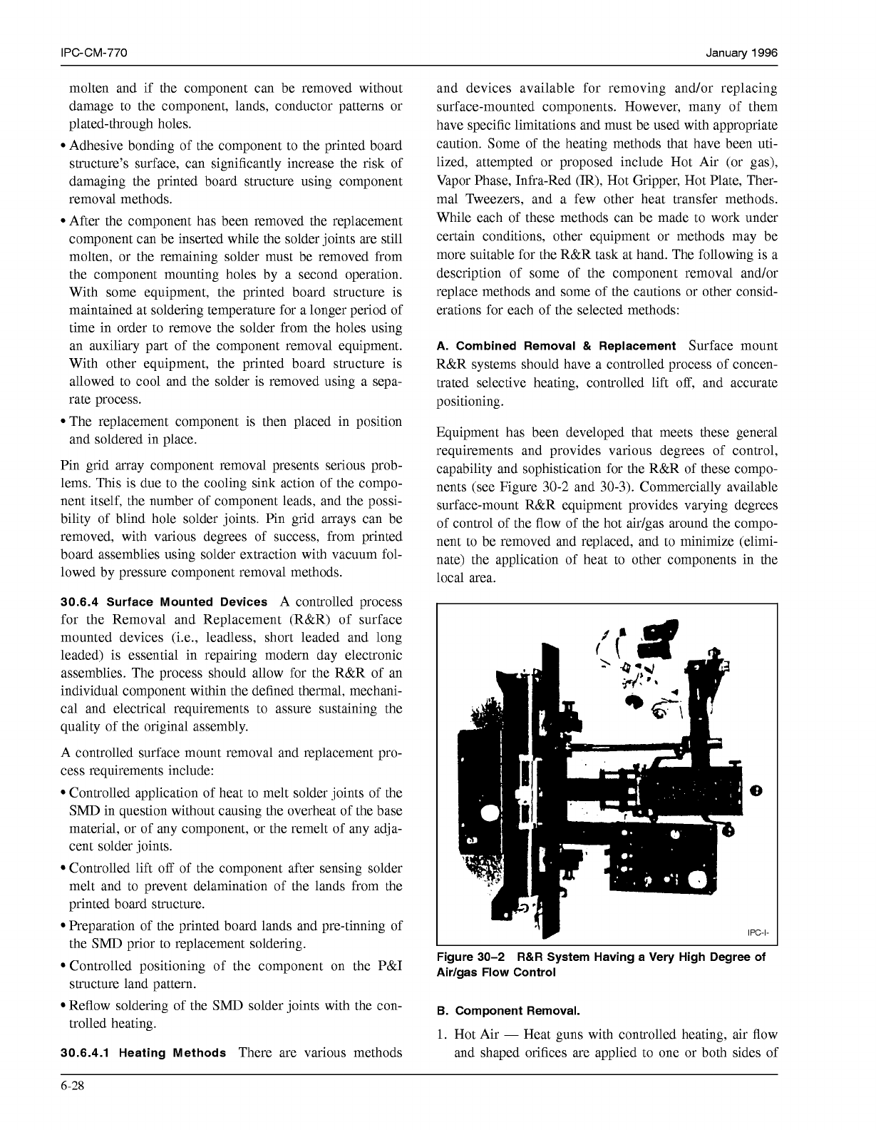
Equipment has been developed that meets these general
requirements and provides various degrees of control,
capability and sophistication for the R&R of these compo-
nents (see Figure
30-2
and
30-3).
Commercially available
surface-mount R&R equipment provides varying degrees
of control of the flow of the hot aidgas around the compo-
nent to be removed and replaced, and to minimize (elimi-
nate) the application of heat to other components in the
local area.
Figure 30-2
R&R
System Having a Very High Degree of
Airlgas Flow Control
B.
Component Removal.
1.
Hot Air
-
Heat guns with controlled heating, air flow
and shaped orifices are applied to one or both sides of
6-28
COPYRIGHT Association Connecting Electronics Industries
Licensed by Information Handling Services
COPYRIGHT Association Connecting Electronics Industries
Licensed by Information Handling Services