IPC-CM-770D-1996 - 第30页
IPC-CM-770 Januaty 1996 0.4 mm Not Recommended Recommended Component mounted flush to prlnted board. Component mounted wlth adequate clearance between end NOTES: 1. The purpose of ralslng the component body off the 2. If…
January
1996
IPC-CM-770
are used in the same assembly is rare to non-existent. Refer
to general information related to class B/1 or
B/2
assem-
blies for consideration when leaded axial surface mount
components are used with chip components. When
through-hole axial components and chip components are
used in the same assembly, care must be taken to establish
proper assembly sequence, design for tool clearances and
shock resistance before soldering, cleaning, inspection/
testing, and rework.
5.5
Manual Assembly
Manual techniques for axial com-
ponents mounting are covered in Section 20.5 of this
guideline.
5.6 Automated Assembly
Automated techniques for
axial component mounting are covered in Section 20.6 of
this guideline. In addition, the following paragraphs repre-
sent additional considerations.
Multiple station sequencers and automatic variable center
distance (VCD) axial component insertion machines can be
utilized to perform high labor content kitting and compo-
nent preparation automatically for manual or operator
assisted component assembly. For this application, the cut
and clinch head of the VCD machine is removed and a
multiple cavity tray is placed in a modified board holder in
place of a printed board.
5.7
Handling and Storage
The handling and storage of
axial-leaded components should be in accordance with the
guidelines of Section 25.
5.10 Conformal Coating
General techniques for confor-
mal coating for all types of assemblies are described in
Section 28.
5.11 Quality Assurance
General quality assurance con-
siderations are described in Section 30.
6.0 RADIAL-LEADED DISCRETE COMPONENTS
Radial-leaded components come in a variety of shapes
from cylindrical, square, rectangular, wafer and kidney.
Leads exit from a common side of the component. The lead
is either ribbon or cylindrical. Selected devices can be
automatically inserted during assembly and also can be
modified with coined leads for surface mounting.
6.1 Part Type Description
Typical types of radial-lead
components are electrolytic, plastic, dipped, molded,
encapsulated capacitors, Figures 6-1, 6-2, 6-3, and transis-
tors, Figure 6-4.
6.1.1 Hermetically Sealed Components
Hermetically
sealed components such as electrolytic capacitors shall be
handled with caution to prevent damage to seals.
Bi-metallic welds should not be stressed.
6.1.2 Plastic Package Components
The integrity of the
interfacial adhesion between the plastic dip coating or
encapsulants to packaging or leads shall be maintained dur-
ing handling.
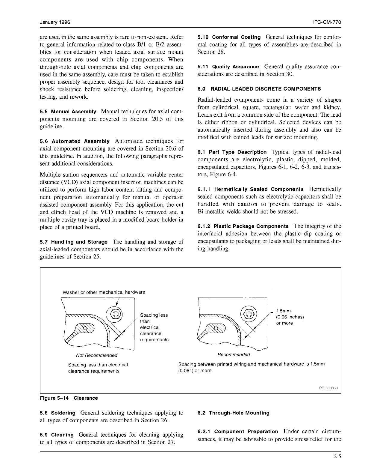
Washer or other mechanical hardware
1.5rnm
or more
Spacing less
(0.06
inches)
than
electrical
clearance
requirements
Not
Recommended
Spacing less than electrical
clearance requirements
Recommended
Spacing between printed wiring and mechancal hardware is 1.5rnm
(0.06")
or
more
IPC-I-O0030
Figure 5-1
4
Clearance
5.8 Soldering
General soldering techniques applying to
6.2 Through-Hole Mounting
all types of components are described in Section 26.
5.9 Cleaning
General techniques for cleaning applying
to all types of components are described in Section 27.
6.2.1 Component Preparation
Under certain circum-
stances, it may be advisable to provide stress relief for the
2-5
COPYRIGHT Association Connecting Electronics Industries
Licensed by Information Handling Services
COPYRIGHT Association Connecting Electronics Industries
Licensed by Information Handling Services
IPC-CM-770
Januaty
1996
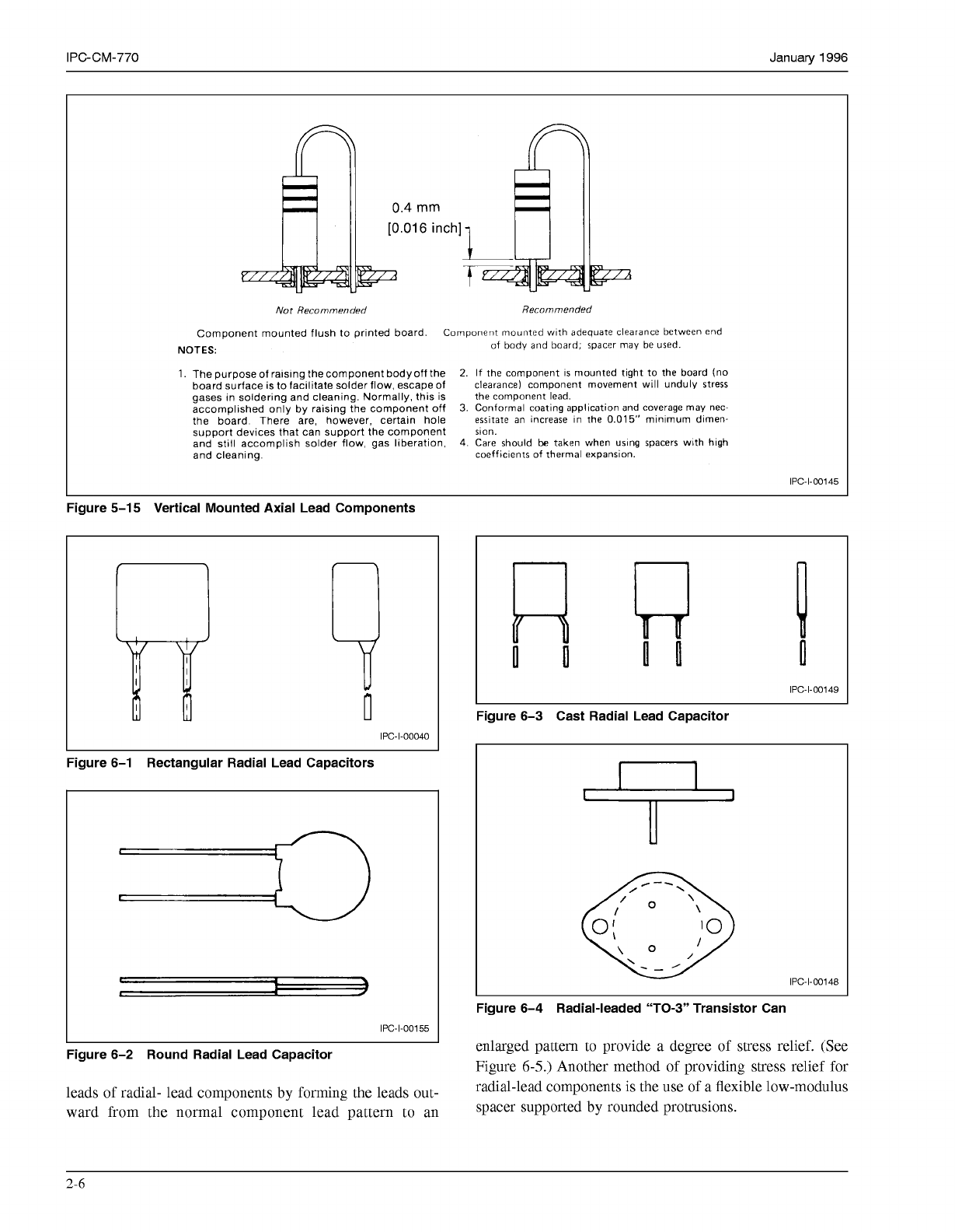
0.4
mm
Not
Recommended Recommended
Component mounted flush to prlnted board. Component mounted wlth adequate clearance between end
NOTES:
1.
The purpose of ralslng the component body off the
2.
If the component
IS
mounted tight to the board
(no
board surface is to facilitate solder flow, escape of
clearance) component movement will unduly Stress
gases in soldering and cleaning. Normally, this
is
the component lead.
accomplished only by raising the component
off
3.
Conformal coating
application
and coverage may nec-
the board There are, however, certain hole
essitate
an increase
In
the
0.015’’
mlnlmum
dlmen-
support devices that can support the component
son.
and still accomplish solder flow, gas liberation,
4.
Care should
be
taken when uslng spacers with
hlgh
and cleaning.
coefficlents of thermal expansion.
of
body and board; spacer may
be
used.
IPC-1-00145
Figure 5-1
5
Vertical Mounted Axial Lead Components
IPc-I-00040
Figure 6-1 Rectangular Radial Lead Capacitors
1
IPC-1-00155
Figure 6-2 Round Radial Lead Capacitor
leads of radial- lead components by forming the leads out-
ward from the normal component lead pattern to an
I
IPC-1-00149
I
Figure 6-3 Cast Radial Lead Capacitor
0
\
/
r”
IPC-1-00148
Figure 6-4 Radial-leaded “TO-3” Transistor Can
enlarged pattern to provide a degree of stress relief. (See
Figure
6-5.)
Another method of providing stress relief for
radial-lead components is the use of a flexible low-modulus
spacer supported by rounded protrusions.
2-6
COPYRIGHT Association Connecting Electronics Industries
Licensed by Information Handling Services
COPYRIGHT Association Connecting Electronics Industries
Licensed by Information Handling Services
January
1996
IPC-CM-770
6.2.2 Land Patterns
Information on land patterns fol-
lows that cited in Section
5.2.2
for axial-leaded compo-
nents.
IPC-1-00183
I
Figure 6-5 Stress Relief Leads
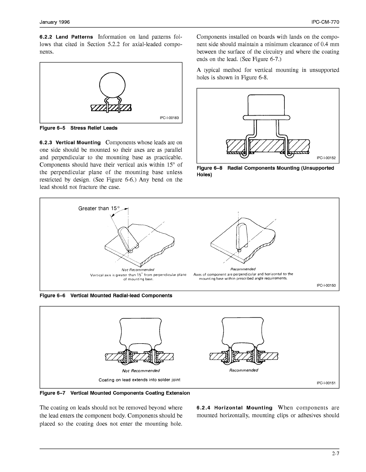
6.2.3 Vertical Mounting
Components whose leads are on
one side should be mounted
so
their axes are as parallel
and perpendicular to the mounting base as practicable.
Components should have their vertical axis within
15"
of
the perpendicular plane of the mounting base unless
restricted by design. (See Figure
6-6.)
Any bend on the
lead should not fracture the case.
Components installed on boards with lands on the compo-
nent side should maintain a minimum clearance of
0.4
mm
between the surface of the circuitry and where the coating
ends on the lead. (See Figure
6-7.)
A typical method for vertical mounting in unsupported
holes is shown in Figure
6-8.
IPC-1-00152
Figure 6-8 Radial Components Mounting (Unsupported
Holes)
Greater than
15
Not
Recommended
Recornmended
Vertical
axis
is
greater than
15''
from perpendlcular plane Axes
of
component are perpendicular and
horizontal
to the
of
mountlng base. mounting base wlthln prescrlbed angle requirements.
IPC-1-00150
Figure 6-6 Vertical Mounted Radial-lead Components
Not
Recommended
Coating on lead extends into solder joint
Recommended
IPC-1-00151
Figure 6-7 Vertical Mounted Components Coating Extension
The coating on leads should not be removed beyond where
6.2.4 Horizontal Mounting
When components are
the lead enters the component body. Components should be mounted horizontally, mounting clips or adhesives should
placed
so
the coating does not enter the mounting hole.
2-7
COPYRIGHT Association Connecting Electronics Industries
Licensed by Information Handling Services
COPYRIGHT Association Connecting Electronics Industries
Licensed by Information Handling Services