IPC-CM-770D-1996 - 第37页
January 1996 IPC-CM-770 Part Three Multiple Leaded Components 8.0 MULTIPLE-RADIAL-LEAD COMPONENTS The packaging technology is well established for transis- tors in metal “TO” cans. This configuration was used for early m…
IPC-CM-770
Januaty
1996
reflowed. Automated board handling facilitates precise and
rapid movement of assemblies through the process.
7.7
Handling and Storage
The handling and storage
of
chip components should be in accordance with the guide-
lines of Section
26.
7.8
Soldering
General soldering techniques applying to
all types of components are described in Section
27.
7.9
Cleaning
General techniques for cleaning applying
to all types of components are described in Section
28.
7.10
Conformal Coating
General techniques for confor-
mal coating for all types of assemblies are described in
Section
29.
2-12
COPYRIGHT Association Connecting Electronics Industries
Licensed by Information Handling Services
COPYRIGHT Association Connecting Electronics Industries
Licensed by Information Handling Services
January
1996
IPC-CM-770
Part Three
Multiple Leaded Components
8.0 MULTIPLE-RADIAL-LEAD COMPONENTS
The packaging technology is well established for transis-
tors in metal “TO” cans. This configuration was used for
early multiple lead components and is still popular today.
Multiple-lead component cans are also available in many
sizes and shapes. The following general considerations
should be taken into account when designing printed board
assemblies with multiple- lead components:
Land size, lead forming and lead clinching.
The physical dimensions of the multiple lead component.
Automatic, semi-automatic, and manual component inser-
tion tolerances and restraints.
Component dimensions and tolerances.
Mechanical securing such as clips, clamps, brackets,
sockets, etc.
8.1 Part Type Description
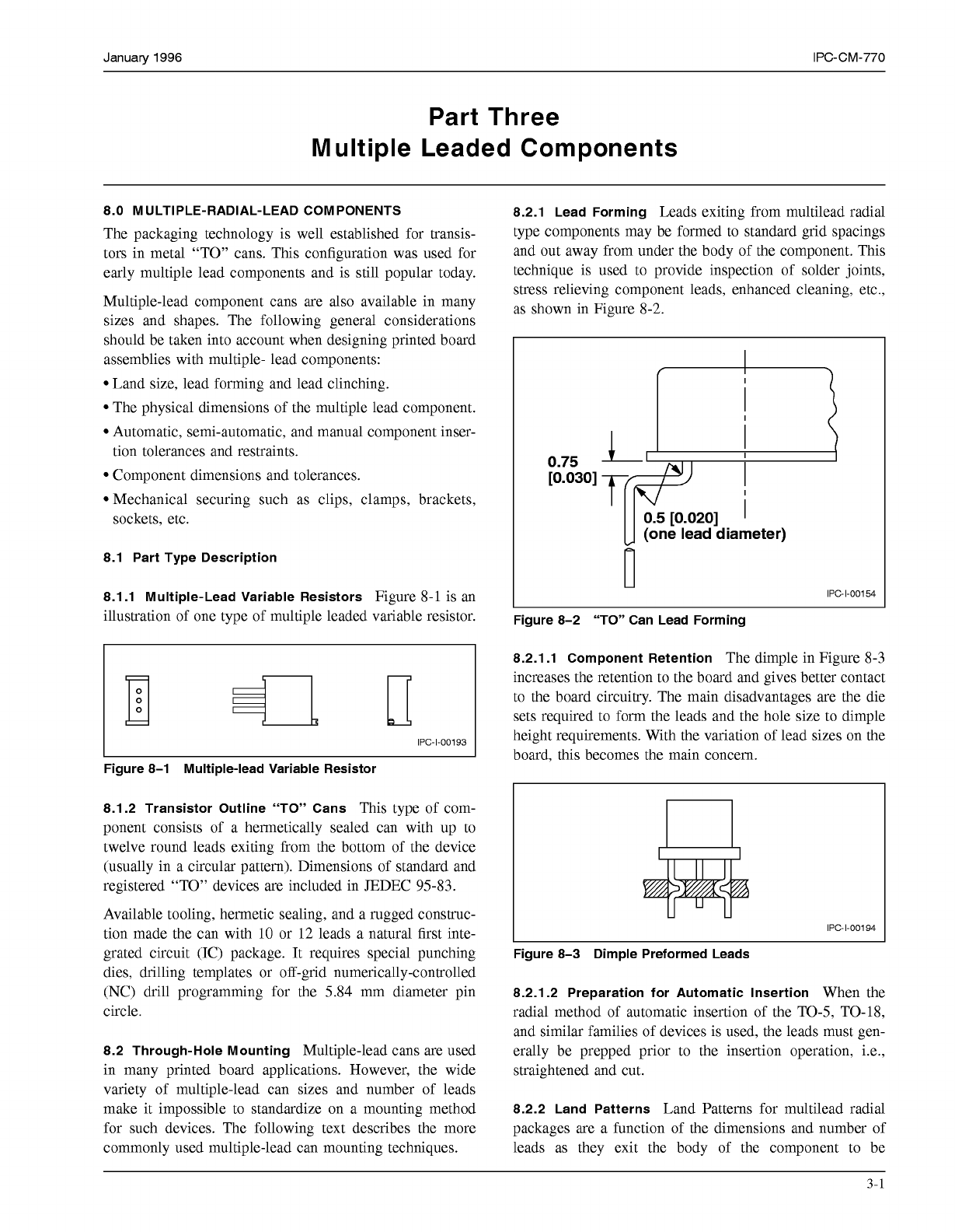
8.1.1 Multiple-Lead Variable Resistors
Figure 8-1 is an
illustration of one type of multiple leaded variable resistor.
IPC-1-00193
Figure 8-1 Multiple-lead Variable Resistor
8.1.2 Transistor Outline “TO” Cans
This type of com-
ponent consists of a hermetically sealed can with up to
twelve round leads exiting from the bottom of the device
(usually in a circular pattern). Dimensions of standard and
registered “TO” devices are included in JEDEC 95-83.
Available tooling, hermetic sealing, and a rugged consmc-
tion made the can with
10
or 12 leads a natural first inte-
grated circuit (IC) package. It requires special punching
dies, drilling templates or off-grid numerically-controlled
(NC) drill programming for the 5.84 mm diameter pin
circle.
8.2 Through-Hole Mounting
Multiple-lead cans are used
in many printed board applications. However, the wide
variety of multiple-lead can sizes and number of leads
make it impossible to standardize on a mounting method
for such devices. The following text describes the more
commonly used multiple-lead can mounting techniques.
8.2.1 Lead Forming
Leads exiting from multilead radial
type components may be formed to standard grid spacings
and out away from under the body of the component. This
technique is used to provide inspection of solder joints,
stress relieving component leads, enhanced cleaning, etc.,
as shown in Figure 8-2.
0.75
yN--
T
II
0.5
[0.020]
I
(one lead diameter)
IPC-1-00154
Figure 8-2 “TO” Can Lead Forming
8.2.1.1 Component Retention
The dimple in Figure 8-3
increases the retention to the board and gives better contact
to the board circuitry. The main disadvantages are the die
sets required to form the leads and the hole size to dimple
height requirements. With the variation of lead sizes on the
board, this becomes the main concern.
IPC-1-00194
Figure 8-3 Dimple Preformed Leads
8.2.1.2 Preparation for Automatic Insertion
When the
radial method of automatic insertion of the TO-5, TO-18,
and similar families of devices is used, the leads must gen-
erally be prepped prior to the insertion operation, i.e.,
straightened and cut.
8.2.2 Land Patterns
Land Patterns for multilead radial
packages are a function of the dimensions and number of
leads as they exit the body of the component to be
3-1
COPYRIGHT Association Connecting Electronics Industries
Licensed by Information Handling Services
COPYRIGHT Association Connecting Electronics Industries
Licensed by Information Handling Services
IPC-CM-770
Januaty
1996
mounted. Pattern configuration will also vary depending
upon the lead forming requirements as with spreader
mounting or reform into alternate patterns. Additional
information for hole/land requirements can be found in
Section 21.
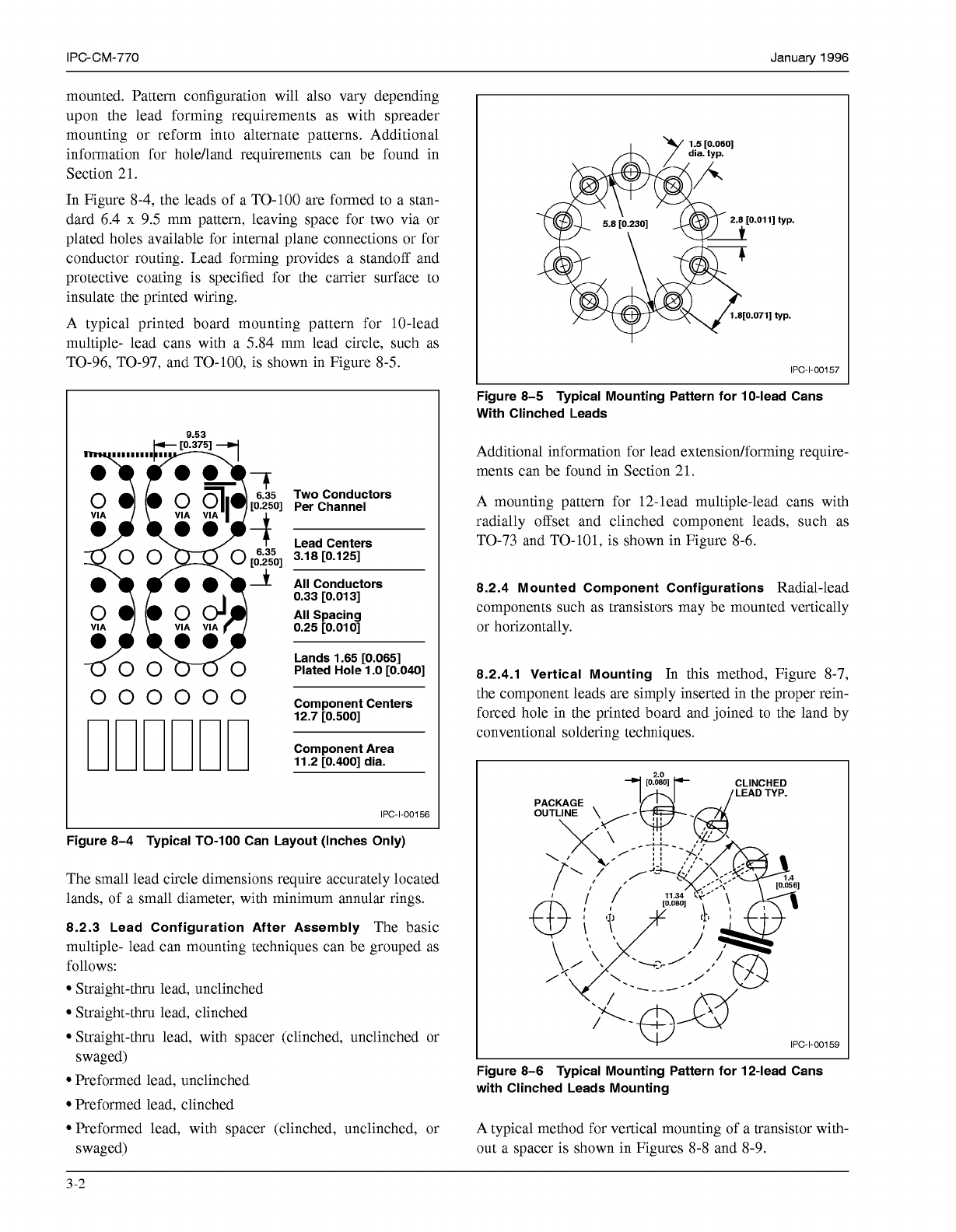
In Figure 8-4, the leads of a TO-100 are formed to a stan-
dard 6.4 x 9.5 mm pattern, leaving space for two via or
plated holes available for internal plane connections or for
conductor routing. Lead forming provides a standoff and
protective coating is specified for the carrier surface to
insulate the printed wiring.
A typical printed board mounting pattern for 10-lead
multiple- lead cans with a 5.84 mm lead circle, such as
TO-96, TO-97, and TO-100, is shown in Figure 8-5.
O
O0
O0
ow0
O000
0000
Two Conductors
Per Channel
Lead Centers
3.18 [0.125]
All Conductors
0.33 [0.013]
All Spacing
0.25 [0.01 O]
Lands 1.65 [0.065]
Plated Hole 1
.O
[0.040]
Component Centers
12.7 [0.500]
Component Area
11.2 [0.400] dia.
IPC-1-00156
Figure 8-4 Typical TO-100 Can Layout (Inches Only)
The small lead circle dimensions require accurately located
lands, of a small diameter, with minimum annular rings.
8.2.3 Lead Configuration After Assembly
The basic
multiple- lead can mounting techniques can be grouped as
follows:
Straight-thru lead, unclinched
Straight-thru lead, clinched
Straight-thru lead, with spacer (clinched, unclinched or
swaged)
Preformed lead, unclinched
Preformed lead, clinched
Preformed lead, with spacer (clinched, unclinched, or
swaged)
1.5
[0.060]
IPC-1-00157
Figure 8-5 Typical Mounting Pattern for 10-lead Cans
With Clinched Leads
Additional information for lead extension/forming require-
ments can be found in Section 21.
A mounting pattern for 12-lead multiple-lead cans with
radially offset and clinched component leads, such as
TO-73 and TO-101, is shown in Figure 8-6.
8.2.4 Mounted Component Configurations
Radial-lead
components such as transistors may be mounted vertically
or horizontally.
8.2.4.1 Vertical Mounting
In this method, Figure 8-7,
the component leads are simply inserted in the proper rein-
forced hole in the printed board and joined to the land by
conventional soldering techniques.
I
IPC-1-00159
Figure 8-6 Typical Mounting Pattern for 12-lead Cans
with Clinched Leads Mounting
A typical method for vertical mounting of a transistor with-
out a spacer is shown in Figures 8-8 and 8-9.
3-2
COPYRIGHT Association Connecting Electronics Industries
Licensed by Information Handling Services
COPYRIGHT Association Connecting Electronics Industries
Licensed by Information Handling Services