IPC-CM-770D-1996 - 第71页
January 1996 IPC-CM-770 internal connectors, but the special board preparation usu- ally results in higher costs. wrap, press-fit pin or solder. Housing enhancements may include card support, printed board, or connector …
IPC-CM-770
Januaty
1996
I I
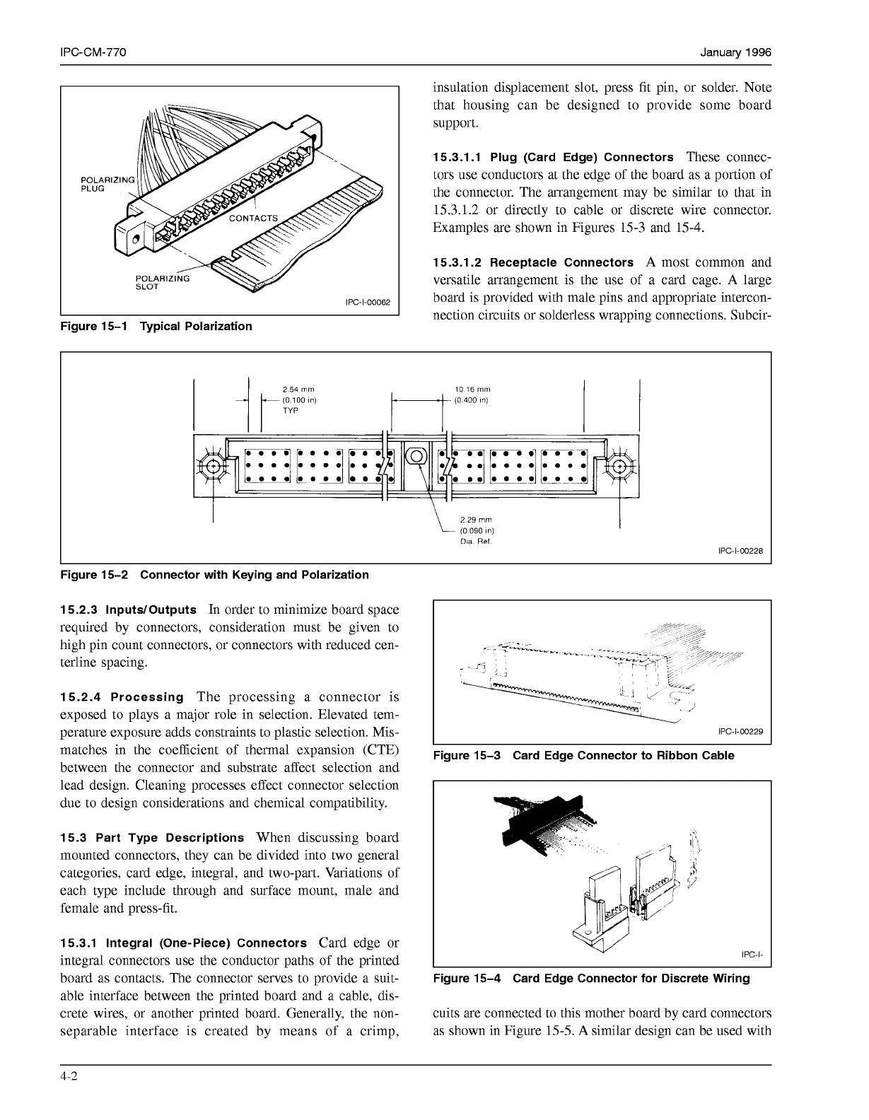
insulation displacement slot, press fit pin, or solder. Note
IPC-I-O0062
Figure 15-1 Typical Polarization
that housing can be designed to provide some board
support.
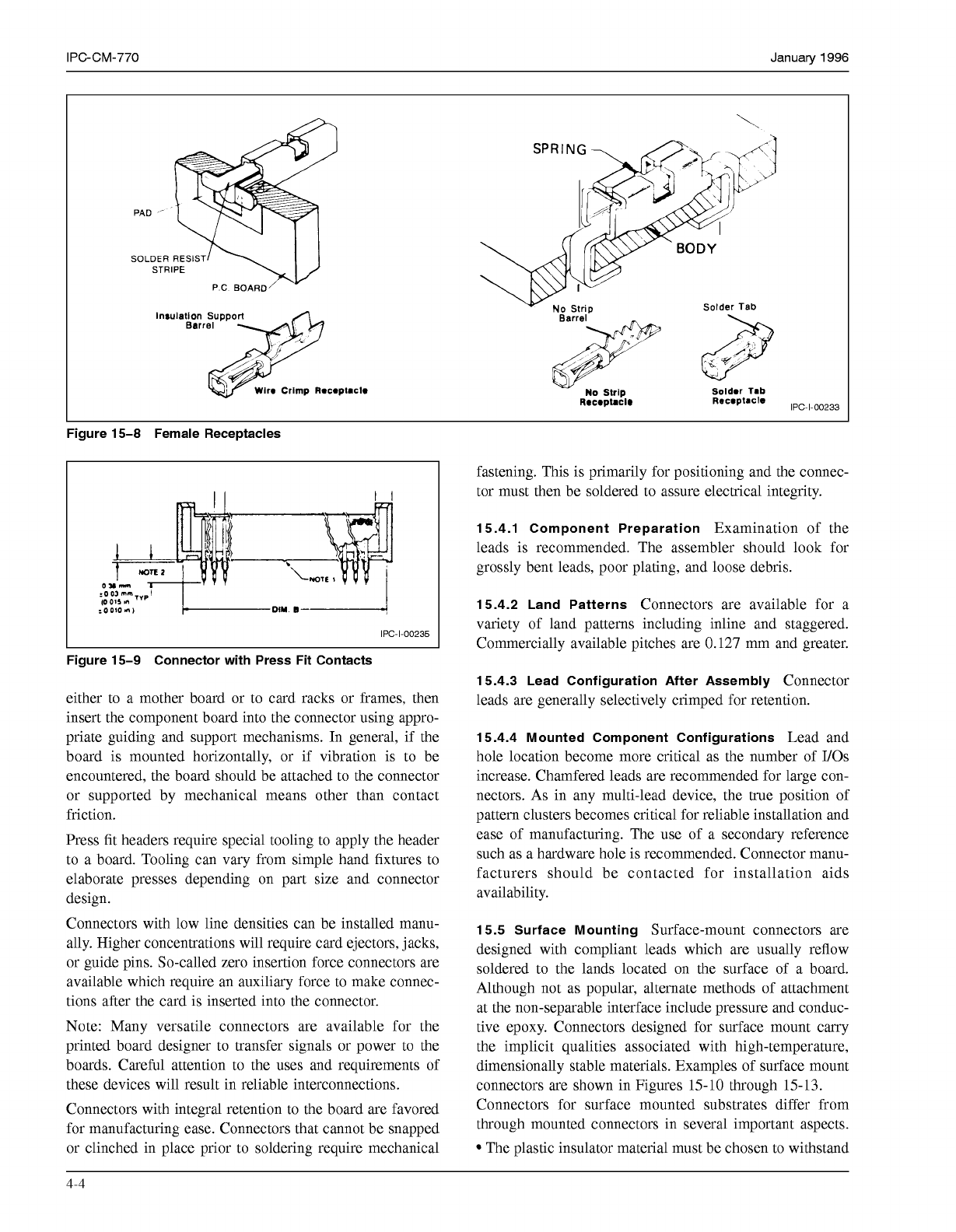
15.3.1.1 Plug (Card Edge) Connectors
These connec-
tors use conductors at the edge of the board as a portion of
the connector. The arrangement may be similar to that in
15.3.1.2
or directly to cable or discrete wire connector.
Examples are shown in Figures
15-3
and
15-4.
15.3.1.2 Receptacle Connectors
A
most common and
versatile arrangement is the use of a card cage.
A
large
board is provided with male pins and appropriate intercon-
nection circuits or solderless wrapping connections. Subcir-
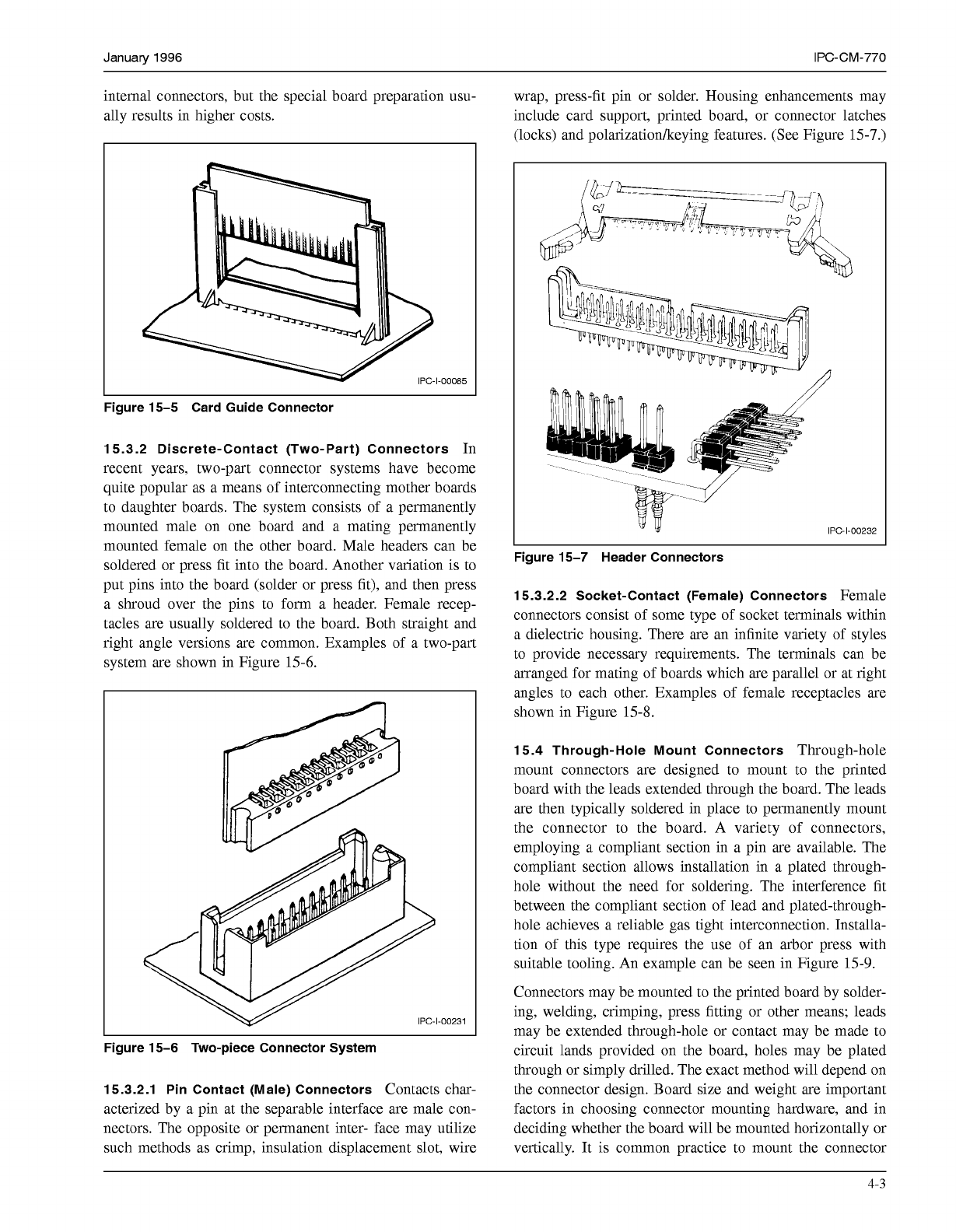
2
54
mm
(O
100
In)
(O
400
In)
10 16
mm
TYP
Dia
Ref
IPC-I-O0228
L
Figure 15-2 Connector with Keying and Polarization
15.2.3 InputdOutputs
In order to minimize board space
required by connectors, consideration must be given to
high pin count connectors, or connectors with reduced cen-
terline spacing.
15.2.4 Processing
The processing a connector is
exposed to plays a major role in selection. Elevated tem-
perature exposure adds constraints to plastic selection. Mis-
matches in the coefficient of thermal expansion (CTE)
I
IPC-I-O0229
Figure 15-3 Card Edge Connector to Ribbon Cable
between the connector and substrate affect selection and
lead design. Cleaning processes effect connector selection
due to design considerations and chemical compatibility.
15.3 Part Type Descriptions
When discussing board
I!
-,
mounted connectors, they can be divided into two general
categories, card edge, integral, and two-part. Variations of
;i
each type include through and surface mount, male and
y
female and press-fit.
15.3.1 Integral (One-Piece) Connectors
Card edge or
integral connectors use the conductor paths of the printed
board as contacts. The connector serves to provide a suit-
Figure 15-4 Card Edge Connector for Discrete Wiring
able interface between the printed board and a cable, dis-
crete wires, or another printed board. Generally, the non- cuits are connected to this mother board by card connectors
separable interface is created by means of a crimp, as shown in Figure
15-5.
A
similar design can be used with
- -
.
.\
IPC-I-
4-2
COPYRIGHT Association Connecting Electronics Industries
Licensed by Information Handling Services
COPYRIGHT Association Connecting Electronics Industries
Licensed by Information Handling Services
January
1996
IPC-CM-770
internal connectors, but the special board preparation usu-
ally results in higher costs.
wrap, press-fit pin or solder. Housing enhancements may
include card support, printed board, or connector latches
(locks) and polarizationkeying features. (See Figure
15-7.)
-1-00085
Figure 15-5 Card Guide Connector
15.3.2 Discrete-Contact (Two-Part) Connectors
In
recent years, two-part connector systems have become
quite popular as a means of interconnecting mother boards
to daughter boards. The system consists of a permanently
mounted male on one board and a mating permanently
mounted female on the other board. Male headers can be
soldered or press fit into the board. Another variation is to
put pins into the board (solder or press fit), and then press
a shroud over the pins to form a header. Female recep-
tacles are usually soldered to the board. Both straight and
right angle versions are common. Examples of a two-part
system are shown in Figure
15-6.
r
Figure 15-6 Two-piece Connector System
15.3.2.1 Pin Contact (Male) Connectors
Contacts char-
acterized by a pin at the separable interface are male con-
nectors. The opposite or permanent inter- face may utilize
such methods as crimp, insulation displacement slot, wire
IPC-1-00232
Figure 15-7 Header Connectors
15.3.2.2 Socket-Contact (Female) Connectors
Female
connectors consist of some type of socket terminals within
a dielectric housing. There are an infinite variety of styles
to provide necessary requirements. The terminals can be
arranged for mating of boards which are parallel or at right
angles to each other. Examples of female receptacles are
shown in Figure
15-8.
15.4 Through-Hole Mount Connectors
Through-hole
mount connectors are designed to mount to the printed
board with the leads extended through the board. The leads
are then typically soldered in place to permanently mount
the connector to the board. A variety of connectors,
employing a compliant section in a pin are available. The
compliant section allows installation in a plated through-
hole without the need for soldering. The interference fit
between the compliant section of lead and plated-through-
hole achieves a reliable gas tight interconnection. Installa-
tion of this type requires the use of an arbor press with
suitable tooling. An example can be seen in Figure
15-9.
Connectors may be mounted to the printed board by solder-
ing, welding, crimping, press fitting or other means; leads
may be extended through-hole or contact may be made to
circuit lands provided on the board, holes may be plated
through or simply drilled. The exact method will depend on
the connector design. Board size and weight are important
factors in choosing connector mounting hardware, and in
deciding whether the board will be mounted horizontally or
vertically. It is common practice to mount the connector
4-3
COPYRIGHT Association Connecting Electronics Industries
Licensed by Information Handling Services
COPYRIGHT Association Connecting Electronics Industries
Licensed by Information Handling Services
IPC-CM-770
Januaty
1996
lnrulallon Support
Wir.
Crimp
Rac*ptmclo
IPC-1-00233
Figure 15-8 Female Receptacles
IPC-1-00235
I
Figure 15-9 Connector with Press Fit Contacts
either to a mother board or to card racks or frames, then
insert the component board into the connector using appro-
priate guiding and support mechanisms. In general, if the
board is mounted horizontally, or if vibration is to be
encountered, the board should be attached to the connector
or supported by mechanical means other than contact
friction.
Press fit headers require special tooling to apply the header
to a board. Tooling can vary from simple hand fixtures to
elaborate presses depending on part size and connector
design.
Connectors with low line densities can be installed manu-
ally. Higher concentrations will require card ejectors, jacks,
or guide pins. So-called zero insertion force connectors are
available which require an auxiliary force to make connec-
tions after the card is inserted into the connector.
Note: Many versatile connectors are available for the
printed board designer to transfer signals or power to the
boards. Careful attention to the uses and requirements of
these devices will result in reliable interconnections.
Connectors with integral retention to the board are favored
for manufacturing ease. Connectors that cannot be snapped
or clinched in place prior to soldering require mechanical
fastening. This is primarily for positioning and the connec-
tor must then be soldered to assure electrical integrity.
15.4.1 Component Preparation
Examination of the
leads is recommended. The assembler should look for
grossly bent leads, poor plating, and loose debris.
15.4.2 Land Patterns
Connectors are available for a
variety of land patterns including inline and staggered.
Commercially available pitches are
0.127
mm and greater.
15.4.3 Lead Configuration After Assembly
Connector
leads are generally selectively crimped for retention.
15.4.4 Mounted Component Configurations
Lead and
hole location become more critical as the number of I/Os
increase. Chamfered leads are recommended for large con-
nectors. As in any multi-lead device, the true position of
pattern clusters becomes critical for reliable installation and
ease of manufacturing. The use of a secondary reference
such as a hardware hole is recommended. Connector manu-
facturers should be contacted for installation aids
availability.
15.5 Surface Mounting
Surface-mount connectors are
designed with compliant leads which are usually reflow
soldered to the lands located on the surface of a board.
Although not as popular, alternate methods of attachment
at the non-separable interface include pressure and conduc-
tive epoxy. Connectors designed for surface mount carry
the implicit qualities associated with high-temperature,
dimensionally stable materials. Examples of surface mount
connectors are shown in Figures
15-10
through
15-13.
Connectors for surface mounted substrates differ from
through mounted connectors in several important aspects.
The plastic insulator material must be chosen to withstand
4-4
COPYRIGHT Association Connecting Electronics Industries
Licensed by Information Handling Services
COPYRIGHT Association Connecting Electronics Industries
Licensed by Information Handling Services