IPC-CM-770D-1996 - 第85页
January 1996 IPC-CM-770 IPC-1-00253 Figure 17-3 Typical Pin Terminals board hole tolerance, and the number of pins to be inserted. In general, the hole and plating tolerances for compliant pins are wider than for non-com…
IPC-CM-770
Januaty
1996
printed boards. To provide mechanical strength to the ter- minal serves as the feed through device through the glass
minal and the resultant connection, most terminals are seal. See Figure
17-3.
designed for through-the-board mounting, either with
crimping, rolling, or flaring on the back side of the board,
or by an interference fit or “press fit” into the board.
Solder-only mounting may be used when the terminals are
only used as test points.
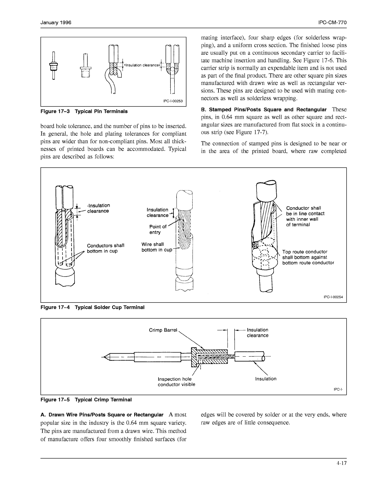
D.
Cup Terminals
cup terminals are not normally
attached to printed boards, but are often used as part of a
connection technique which does interface with a printed
board. Cup terminals are designed for either soldering (see
Figure
17-4)
or crimping (see Figure
17-5).
Terminals can be generally categorized as follows:
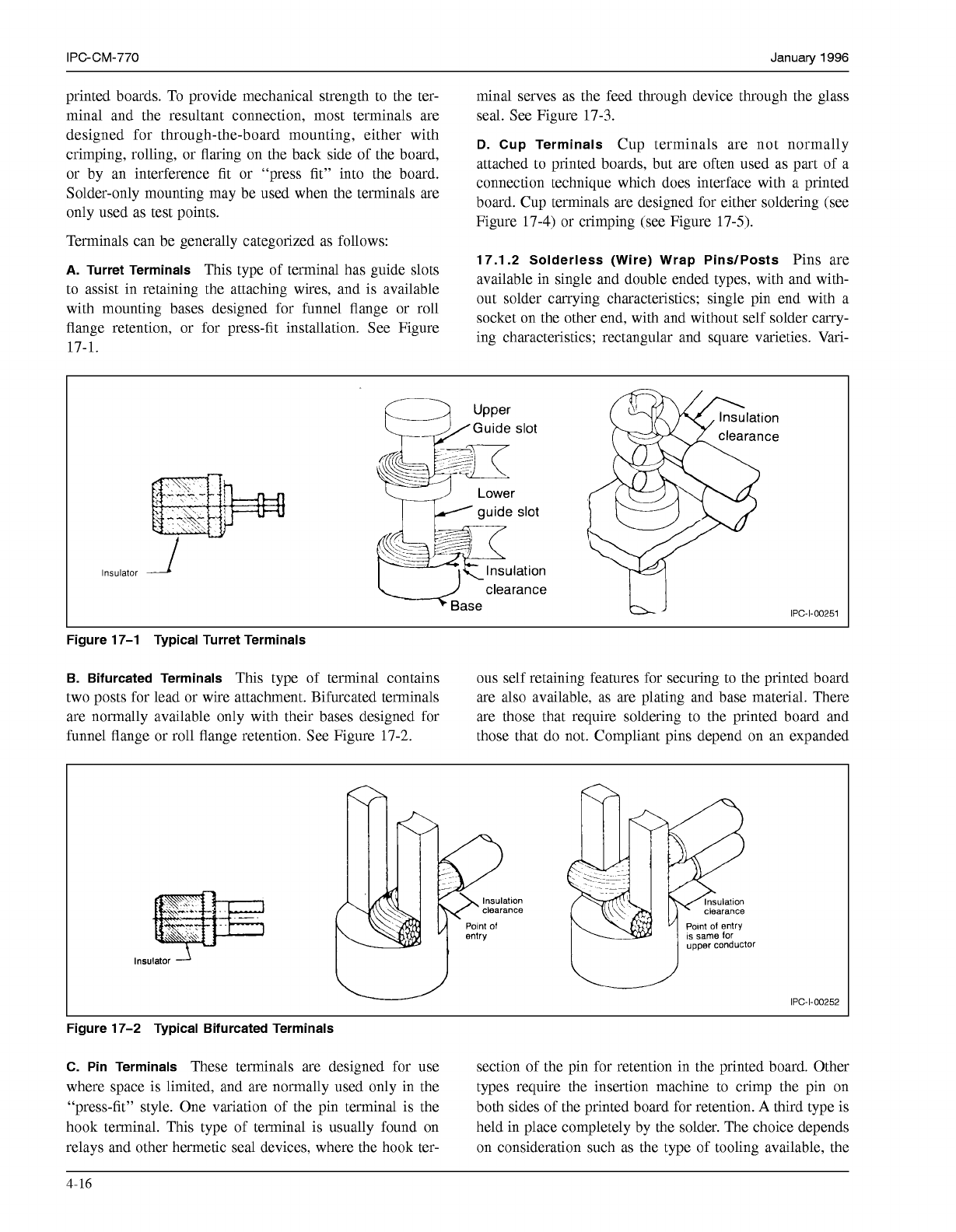
A.
Turret Terminals
This type of terminal has guide slots
to assist in retaining the attaching wires, and is available
with mounting bases designed for funnel flange or roll
flange retention, or for press-fit installation. See Figure
17.1.2 Solderless (Wire) Wrap PinslPosts
Pins are
available in single and double ended types, with and with-
out solder carrying characteristics; single pin end with a
socket on the other end, with and without self solder carry-
ing characteristics; rectangular and square varieties. Vari-
17-1.
I
guide
slot
dase
clearance
IPC-I-O0251
Figure 17-1 Typical Turret Terminals
B. Bifurcated Terminals
This type of terminal contains ous self retaining features for securing to the printed board
two posts for lead or wire attachment. Bifurcated terminals are also available, as are plating and base material. There
are normally available only with their bases designed for are those that require soldering to the printed board and
funnel flange or roll flange retention. See Figure
17-2.
those that do not. Compliant pins depend on an expanded
lnsulatlon
clearance
Polnt
o1
entry
IS
same for
upper conductor
IPC-I-O0252
Figure 17-2 Typical Bifurcated Terminals
C. Pin Terminals
These terminals are designed for use section of the pin for retention in the printed board. Other
where space is limited, and are normally used only in the types require the insertion machine to crimp the pin on
“press-fit’’ style. One variation of the pin terminal is the both sides of the printed board for retention.
A
third type is
hook terminal. This type of terminal is usually found on held in place completely by the solder. The choice depends
relays and other hermetic seal devices, where the hook ter- on consideration such as the type of tooling available, the
4-16
COPYRIGHT Association Connecting Electronics Industries
Licensed by Information Handling Services
COPYRIGHT Association Connecting Electronics Industries
Licensed by Information Handling Services
January
1996
IPC-CM-770
IPC-1-00253
Figure 17-3 Typical Pin Terminals
board hole tolerance, and the number of pins to be inserted.
In general, the hole and plating tolerances for compliant
pins are wider than for non-compliant pins. Most all thick-
nesses of printed boards can be accommodated. Typical
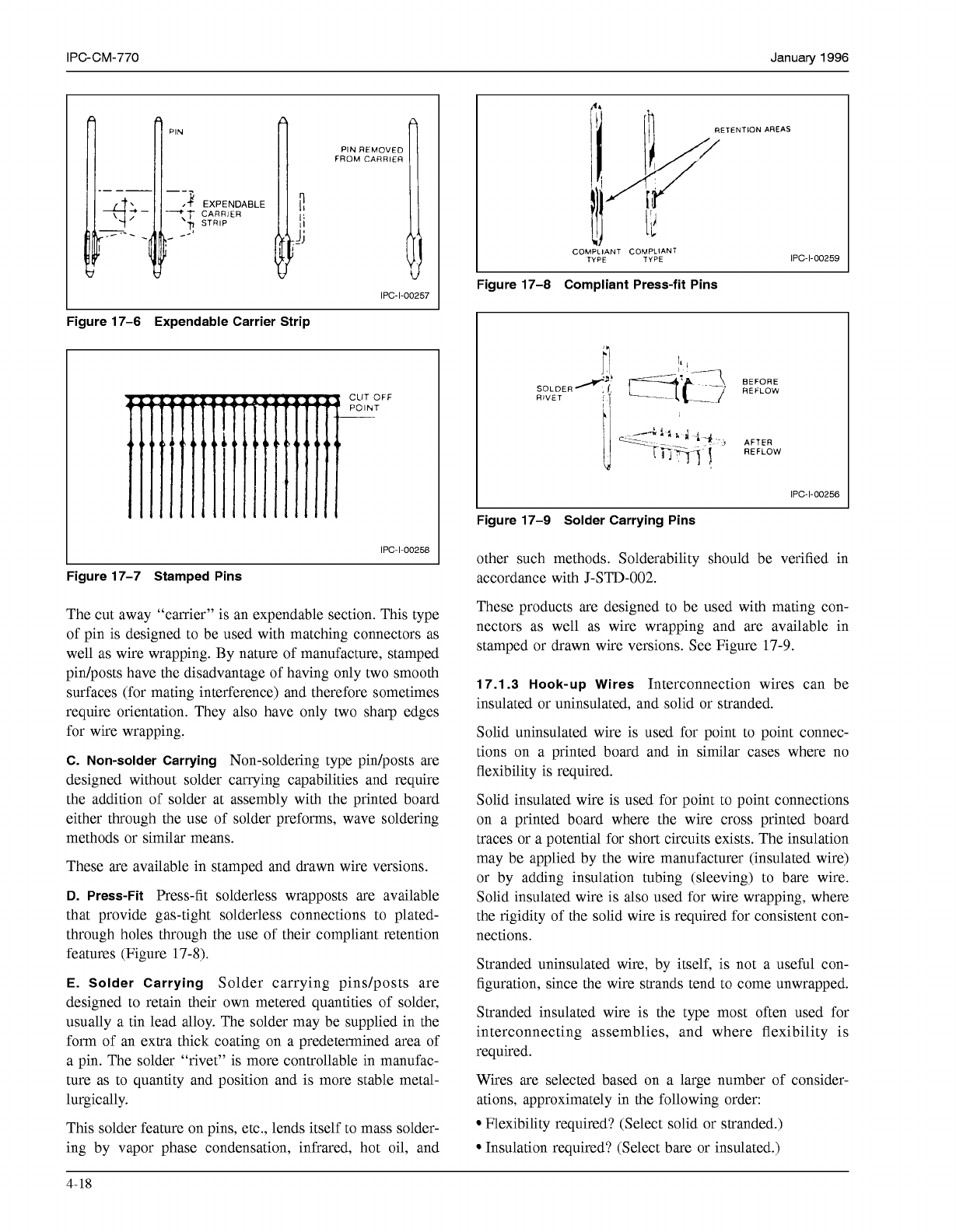
mating interface), four sharp edges (for solderless wrap-
ping), and a uniform cross section. The finished loose pins
are usually put on a continuous secondary carrier to facili-
tate machine insertion and handling. See Figure 17-6. This
carrier strip is normally an expendable item and is not used
as part of the final product. There are other square pin sizes
manufactured with drawn wire as well as rectangular ver-
sions. These pins are designed to be used with mating con-
nectors as well as solderless wrapping.
B.
Stamped PinslPosts Square and Rectangular
These
pins, in 0.64 mm square as well as other square and rect-
angular sizes are manufactured from flat stock in a continu-
ous strip (see Figure 17-7).
The connection of stamped pins is designed to be near or
in the area of the minted board. where raw comnleted
pins are described as follows:
-Insulation
'
clearance
Conductors shall
bottom in cup
Conductor shall
be in line contact
with inner wall
of
terminal
Top route conductor
shall bottom against
bottom route conductor
L
IPC-1-00254
Figure 17-4 Typical Solder Cup Terminal
Insulation
clearance
Inspection hole
conductor visible
Insulation
IPC-I-
Figure 17-5 Typical Crimp Terminal
A.
Drawn Wire PinslPosts Square or Rectangular
A
most edges will be covered by solder or at the very ends, where
popular size in the industry is the 0.64 mm square variety. raw edges are of little consequence.
The pins are manufactured from a drawn wire. This method
of manufacture offers four smoothly finished surfaces (for
4-17
COPYRIGHT Association Connecting Electronics Industries
Licensed by Information Handling Services
COPYRIGHT Association Connecting Electronics Industries
Licensed by Information Handling Services
IPC-CM-770
Januaty
1996
PIN
CARRIER
EXPENDABLE
STRIP
I
IPC-1-00257
I
Figure 17-6 Expendable Carrier Strip
IPC-1-00258
Figure 17-7 Stamped Pins
The cut away “carrier” is an expendable section. This type
of pin is designed to be used with matching connectors as
well as wire wrapping. By nature of manufacture, stamped
pin/posts have the disadvantage of having only two smooth
surfaces (for mating interference) and therefore sometimes
require orientation. They also have only two sharp edges
for wire wrapping.
C. Non-solder Carrying
Non-soldering type pin/posts are
designed without solder carrying capabilities and require
the addition of solder at assembly with the printed board
either through the use of solder preforms, wave soldering
methods or similar means.
These are available in stamped and drawn wire versions.
D.
Press-Fit
Press-fit solderless wrapposts are available
that provide gas-tight solderless connections to plated-
through holes through the use of their compliant retention
features (Figure
17-8).
E. Solder Carrying
Solder carrying pindposts are
designed to retain their own metered quantities of solder,
usually a tin lead alloy. The solder may be supplied in the
form of an extra thick coating on a predetermined area of
a pin. The solder “rivet” is more controllable in manufac-
ture as to quantity and position and is more stable metal-
lurgically.
This solder feature on pins, etc., lends itself to mass solder-
ing by vapor phase condensation, infrared, hot oil, and
‘4.
RETENTION AREAS
COMPLIANT COMPLIANT
TYPE TYPE
IPC-1-00259
Figure 17-8 Compliant Press-fit Pins
IPC-1-00256
Figure 17-9 Solder Carrying Pins
other such methods. Solderability should be verified in
accordance with
J-STD-002.
These products are designed to be used with mating con-
nectors as well as wire wrapping and are available in
stamped or drawn wire versions. See Figure
17-9.
17.1.3 Hook-up Wires
Interconnection wires can be
insulated or uninsulated, and solid or stranded.
Solid uninsulated wire is used for point to point connec-
tions on a printed board and in similar cases where no
flexibility is required.
Solid insulated wire is used for point to point connections
on a printed board where the wire cross printed board
traces or a potential for short circuits exists. The insulation
may be applied by the wire manufacturer (insulated wire)
or by adding insulation tubing (sleeving) to bare wire.
Solid insulated wire is also used for wire wrapping, where
the rigidity of the solid wire is required for consistent con-
nections.
Stranded uninsulated wire, by itself, is not a useful con-
figuration, since the wire strands tend to come unwrapped.
Stranded insulated wire is the type most often used for
interconnecting assemblies, and where flexibility is
required.
Wires are selected based on a large number of consider-
ations, approximately in the following order:
Flexibility required? (Select solid or stranded.)
Insulation required? (Select bare or insulated.)
4-18
COPYRIGHT Association Connecting Electronics Industries
Licensed by Information Handling Services
COPYRIGHT Association Connecting Electronics Industries
Licensed by Information Handling Services