IPC-CM-770D-1996 - 第86页
IPC-CM-770 Januaty 1996 PIN CARRIER EXPENDABLE STRIP I IPC-1-00257 I Figure 17-6 Expendable Carrier Strip IPC-1-00258 Figure 17-7 Stamped Pins The cut away “carrier” is an expendable section. This type of pin is designed…
January
1996
IPC-CM-770
IPC-1-00253
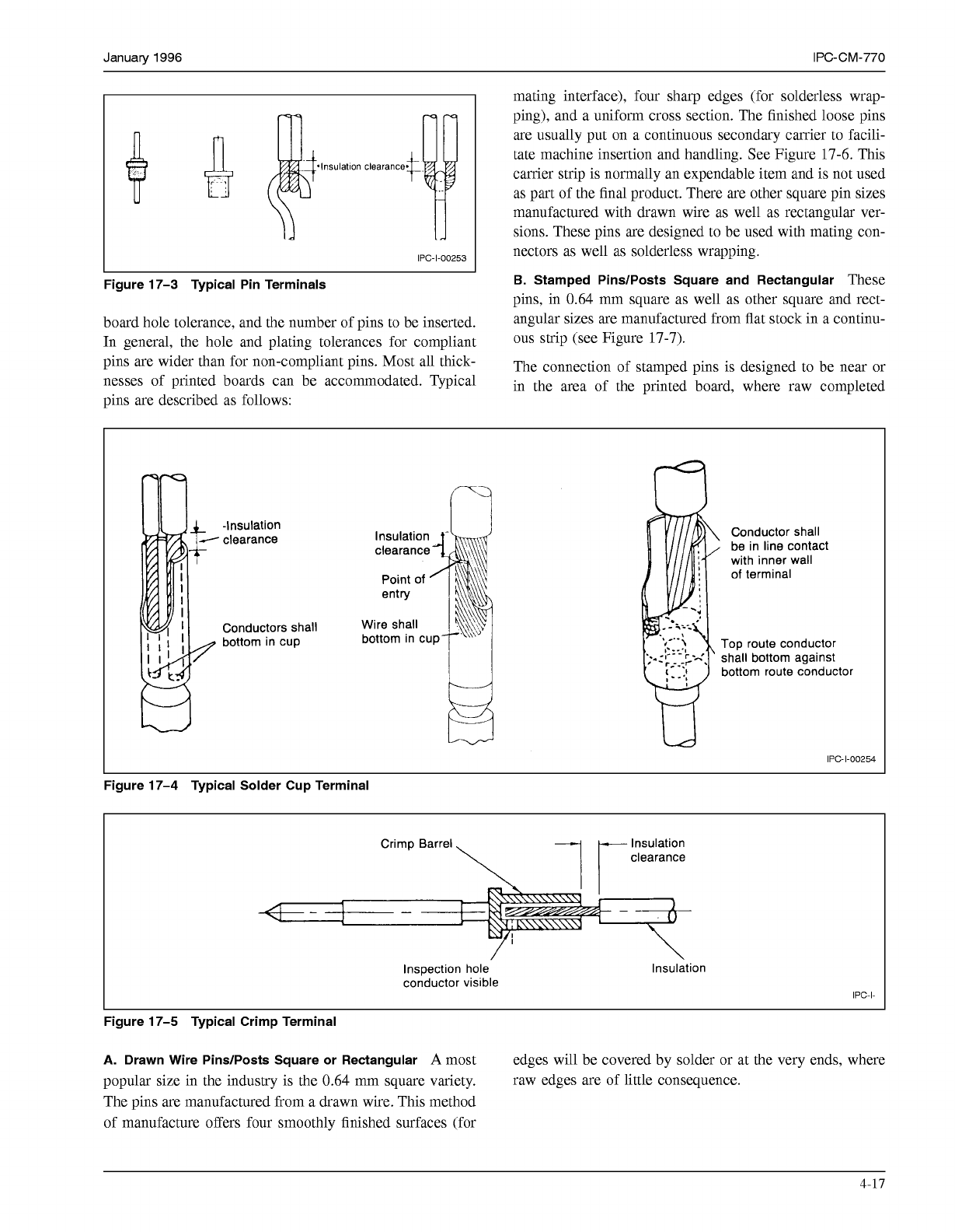
Figure 17-3 Typical Pin Terminals
board hole tolerance, and the number of pins to be inserted.
In general, the hole and plating tolerances for compliant
pins are wider than for non-compliant pins. Most all thick-
nesses of printed boards can be accommodated. Typical
mating interface), four sharp edges (for solderless wrap-
ping), and a uniform cross section. The finished loose pins
are usually put on a continuous secondary carrier to facili-
tate machine insertion and handling. See Figure 17-6. This
carrier strip is normally an expendable item and is not used
as part of the final product. There are other square pin sizes
manufactured with drawn wire as well as rectangular ver-
sions. These pins are designed to be used with mating con-
nectors as well as solderless wrapping.
B.
Stamped PinslPosts Square and Rectangular
These
pins, in 0.64 mm square as well as other square and rect-
angular sizes are manufactured from flat stock in a continu-
ous strip (see Figure 17-7).
The connection of stamped pins is designed to be near or
in the area of the minted board. where raw comnleted
pins are described as follows:
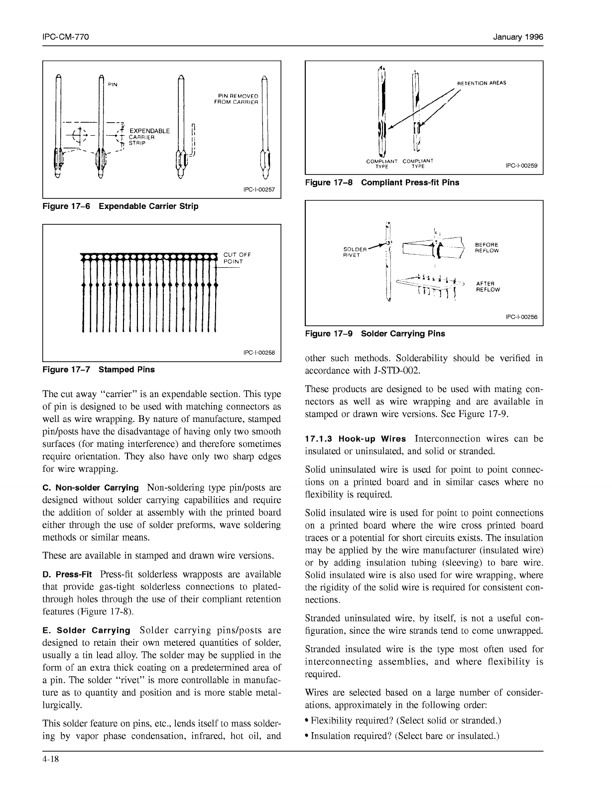
-Insulation
'
clearance
Conductors shall
bottom in cup
Conductor shall
be in line contact
with inner wall
of
terminal
Top route conductor
shall bottom against
bottom route conductor
L
IPC-1-00254
Figure 17-4 Typical Solder Cup Terminal
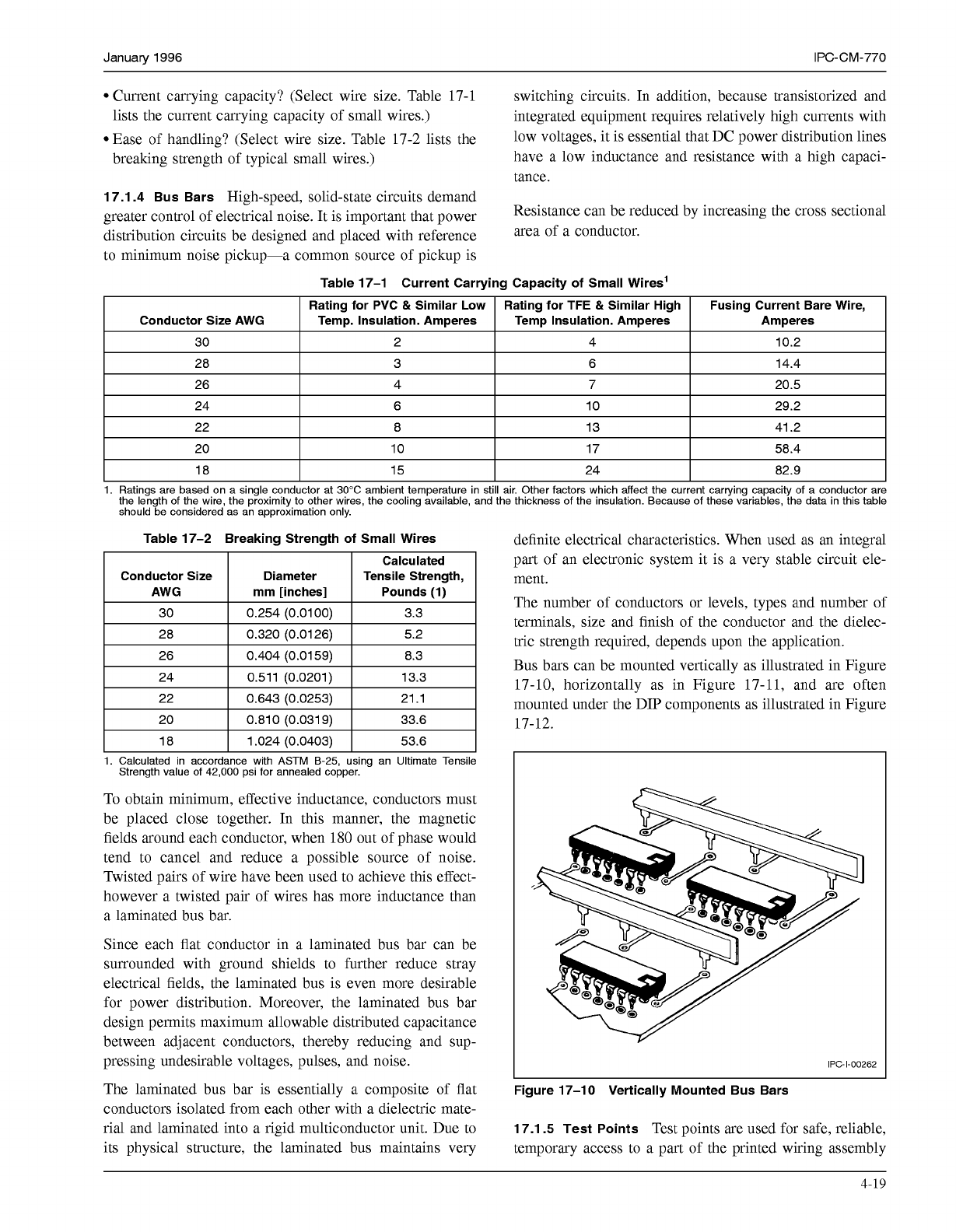
Insulation
clearance
Inspection hole
conductor visible
Insulation
IPC-I-
Figure 17-5 Typical Crimp Terminal
A.
Drawn Wire PinslPosts Square or Rectangular
A
most edges will be covered by solder or at the very ends, where
popular size in the industry is the 0.64 mm square variety. raw edges are of little consequence.
The pins are manufactured from a drawn wire. This method
of manufacture offers four smoothly finished surfaces (for
4-17
COPYRIGHT Association Connecting Electronics Industries
Licensed by Information Handling Services
COPYRIGHT Association Connecting Electronics Industries
Licensed by Information Handling Services
IPC-CM-770
Januaty
1996
PIN
CARRIER
EXPENDABLE
STRIP
I
IPC-1-00257
I
Figure 17-6 Expendable Carrier Strip
IPC-1-00258
Figure 17-7 Stamped Pins
The cut away “carrier” is an expendable section. This type
of pin is designed to be used with matching connectors as
well as wire wrapping. By nature of manufacture, stamped
pin/posts have the disadvantage of having only two smooth
surfaces (for mating interference) and therefore sometimes
require orientation. They also have only two sharp edges
for wire wrapping.
C. Non-solder Carrying
Non-soldering type pin/posts are
designed without solder carrying capabilities and require
the addition of solder at assembly with the printed board
either through the use of solder preforms, wave soldering
methods or similar means.
These are available in stamped and drawn wire versions.
D.
Press-Fit
Press-fit solderless wrapposts are available
that provide gas-tight solderless connections to plated-
through holes through the use of their compliant retention
features (Figure
17-8).
E. Solder Carrying
Solder carrying pindposts are
designed to retain their own metered quantities of solder,
usually a tin lead alloy. The solder may be supplied in the
form of an extra thick coating on a predetermined area of
a pin. The solder “rivet” is more controllable in manufac-
ture as to quantity and position and is more stable metal-
lurgically.
This solder feature on pins, etc., lends itself to mass solder-
ing by vapor phase condensation, infrared, hot oil, and
‘4.
RETENTION AREAS
COMPLIANT COMPLIANT
TYPE TYPE
IPC-1-00259
Figure 17-8 Compliant Press-fit Pins
IPC-1-00256
Figure 17-9 Solder Carrying Pins
other such methods. Solderability should be verified in
accordance with
J-STD-002.
These products are designed to be used with mating con-
nectors as well as wire wrapping and are available in
stamped or drawn wire versions. See Figure
17-9.
17.1.3 Hook-up Wires
Interconnection wires can be
insulated or uninsulated, and solid or stranded.
Solid uninsulated wire is used for point to point connec-
tions on a printed board and in similar cases where no
flexibility is required.
Solid insulated wire is used for point to point connections
on a printed board where the wire cross printed board
traces or a potential for short circuits exists. The insulation
may be applied by the wire manufacturer (insulated wire)
or by adding insulation tubing (sleeving) to bare wire.
Solid insulated wire is also used for wire wrapping, where
the rigidity of the solid wire is required for consistent con-
nections.
Stranded uninsulated wire, by itself, is not a useful con-
figuration, since the wire strands tend to come unwrapped.
Stranded insulated wire is the type most often used for
interconnecting assemblies, and where flexibility is
required.
Wires are selected based on a large number of consider-
ations, approximately in the following order:
Flexibility required? (Select solid or stranded.)
Insulation required? (Select bare or insulated.)
4-18
COPYRIGHT Association Connecting Electronics Industries
Licensed by Information Handling Services
COPYRIGHT Association Connecting Electronics Industries
Licensed by Information Handling Services
January
1996 IPC-CM-770
Current carrying capacity? (Select wire size. Table 17-1 switching circuits. In addition, because transistorized and
lists the current carrying capacity of small wires.)
integrated equipment requires relatively high currents with
Ease of handling? (Select wire size. Table 17-2 lists the
low voltages, it is essential that DC power distribution lines
breaking strength of typical small wires.)
have a low inductance and resistance with a high capaci-
tance.
17.1.4 Bus Bars
High-speed, solid-state circuits demand
distribution circuits be designed and placed with reference
area
Of
a
conductor.
to minimum noise pickup-a common source of pickup is
greater control of electrical noise. It is important that power Resistance can be reduced by increasing the cross sectional
Table 17-1 Current Carrying Capacity
of
Small Wires’
Rating for PVC
&
Similar
Low
Fusing Current Bare Wire, Rating for TFE
&
Similar High
Conductor Size AWG
Amperes
Temp Insulation. Amperes Temp. Insulation. Amperes
30
20.5 7 4 26
14.4 6 3 28
10.2 4 2
I
24
I
6
I
10
I
29.2
I
22
I
8
I
13
I
41.2
I
20
I
10
I
17
I
58.4
I
18 82.9 24 15
1.
Ratings are based on a single conductor at 30°C ambient temperature in still air. Other factors which affect the current carrying capacity of a conductor are
the length of the wire, the proximity to other wires, the cooling available, and the thickness of the insulation. Because of these variables, the data in this table
should be considered as an approximation only.
Table 17-2 Breaking Strength
of
Small Wires
Conductor Size
1.
Calculated in accordance with ASTM B-25, using an Ultimate Tensile
Strength value of 42,000 psi for annealed copper.
To obtain minimum, effective inductance, conductors must
be placed close together. In this manner, the magnetic
fields around each conductor, when
180
out of phase would
tend to cancel and reduce a possible source of noise.
Twisted pairs of wire have been used to achieve this effect-
however a twisted pair of wires has more inductance than
a laminated bus bar.
Since each flat conductor in a laminated bus bar can be
surrounded with ground shields to further reduce stray
electrical fields, the laminated bus is even more desirable
for power distribution. Moreover, the laminated bus bar
design permits maximum allowable distributed capacitance
between adjacent conductors, thereby reducing and sup-
pressing undesirable voltages, pulses, and noise.
The laminated bus bar is essentially a composite of flat
conductors isolated from each other with a dielectric mate-
rial and laminated into a rigid multiconductor unit. Due to
its physical structure, the laminated bus maintains very
definite electrical characteristics. When used as an integral
part of an electronic system it is a very stable circuit ele-
ment.
The number of conductors or levels, types and number of
terminals, size and finish of the conductor and the dielec-
tric strength required, depends upon the application.
Bus bars can be mounted vertically as illustrated in Figure
17-10, horizontally as in Figure 17-11, and are often
mounted under the DIP components as illustrated in Figure
17-12.
I
IPC-1-00262
Figure 17-10 Vertically Mounted Bus Bars
17.1.5 Test Points
Test points are used for safe, reliable,
temporary access to a part of the printed wiring assembly
4-19
COPYRIGHT Association Connecting Electronics Industries
Licensed by Information Handling Services
COPYRIGHT Association Connecting Electronics Industries
Licensed by Information Handling Services