IPC-CM-770D-1996 - 第92页
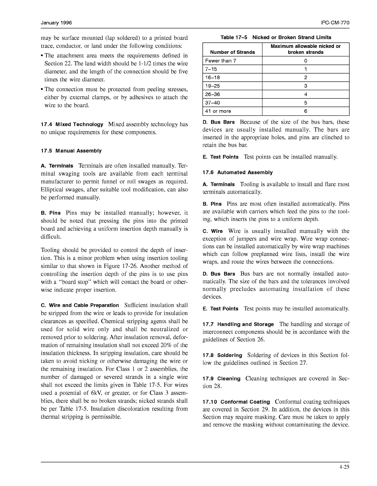
IPC-CM-770 Januaty 1996 17-24). The number of turns required will depend on the gauge of the wire used. Wrapost Apex Wrapost 2 3 Level Wrapper Turn Insulated Wire 2 2 Level - 2 1 Level IPC-1-00273 Figure 17-23 “Wrapping …
January
1996
IPC-CM-770
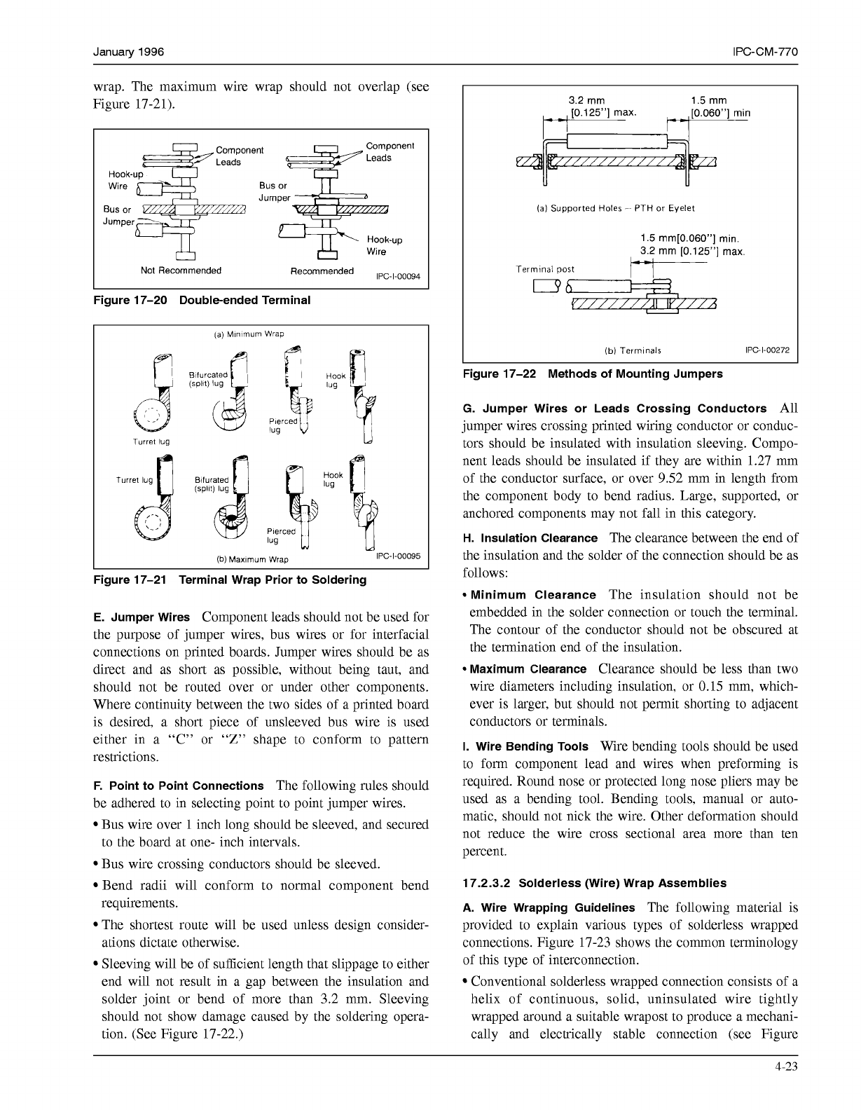
wrap. The maximum wire wrap should not overlap (see
Figure 17-21).
I I
W
Hook-up
Figure 17-20 Double-ended Terminal
(a)
Mlnlmum
Wrap
I
Blfurcated
(SPllt)
lug
Turret
lug
I
(b)
Maxlmum Wrap
Hook
lug
\
IPC
-1-00095
L
Figure 17-21 Terminal Wrap Prior to Soldering
E.
Jumper Wires
Component leads should not be used for
the purpose of jumper wires, bus wires or for interfacial
connections on printed boards. Jumper wires should be as
direct and as short as possible, without being taut, and
should not be routed over or under other components.
Where continuity between the two sides of a printed board
is desired, a short piece of unsleeved bus wire is used
either in a “C” or “Z” shape to conform to pattern
restrictions.
F. Point to Point Connections
The following rules should
be adhered to in selecting point to point jumper wires.
Bus wire over
1
inch long should be sleeved, and secured
to the board at one- inch intervals.
Bus wire crossing conductors should be sleeved.
Bend radii will conform to normal component bend
requirements.
The shortest route will be used unless design consider-
ations dictate otherwise.
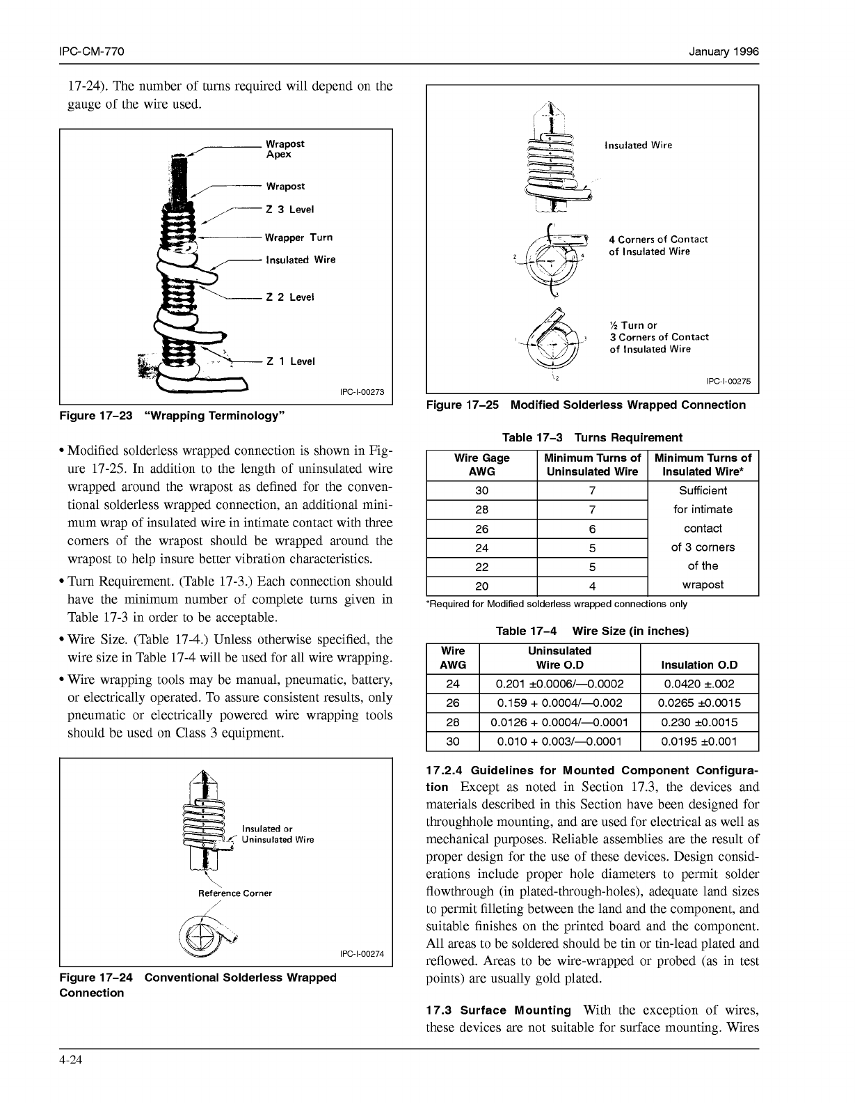
Sleeving will be of sufficient length that slippage to either
end will not result in a gap between the insulation and
solder joint or bend of more than 3.2 mm. Sleeving
should not show damage caused by the soldering opera-
tion. (See Figure 17-22.)
3.2 mm 1.5 mm
-
,
[0.125”] max.
,
[0.060”] min
-
-
(al
Supported
Holes
-~
PTH
or
Eyelet
1.5 mm[0.060”] min.
r3i; mm [0.125”] max
Terrnlnal
post
i-
v///////a///A
(b)
Termlnals
IPC-1-00272
Figure 17-22 Methods
of
Mounting Jumpers
G. Jumper Wires or Leads Crossing Conductors
All
jumper wires crossing printed wiring conductor or conduc-
tors should be insulated with insulation sleeving. Compo-
nent leads should be insulated if they are within 1.27 mm
of the conductor surface, or over 9.52 mm in length from
the component body to bend radius. Large, supported, or
anchored components may not fall in this category.
H.
Insulation Clearance
The clearance between the end of
the insulation and the solder of the connection should be as
follows:
Minimum Clearance
The insulation should not be
embedded in the solder connection or touch the terminal.
The contour of the conductor should not be obscured at
the termination end of the insulation.
Maximum Clearance
Clearance should be less than two
wire diameters including insulation, or
0.15
mm, which-
ever is larger, but should not permit shorting to adjacent
conductors or terminals.
1.
Wire Bending Tools
Wire bending tools should be used
to form component lead and wires when preforming is
required. Round nose or protected long nose pliers may be
used as a bending tool. Bending tools, manual or auto-
matic, should not nick the wire. Other deformation should
not reduce the wire cross sectional area more than ten
percent.
17.2.3.2 Solderless (Wire) Wrap Assemblies
A. Wire Wrapping Guidelines
The following material is
provided to explain various types of solderless wrapped
connections. Figure 17-23 shows the common terminology
of this type of interconnection.
Conventional solderless wrapped connection consists of a
helix of continuous, solid, uninsulated wire tightly
wrapped around a suitable wrapost to produce a mechani-
cally and electrically stable connection (see Figure
4-23
COPYRIGHT Association Connecting Electronics Industries
Licensed by Information Handling Services
COPYRIGHT Association Connecting Electronics Industries
Licensed by Information Handling Services
IPC-CM-770 Januaty 1996
17-24). The number of turns required will depend on the
gauge of the wire used.
Wrapost
Apex
Wrapost
2
3
Level
Wrapper Turn
Insulated Wire
2
2
Level
-
2
1
Level
IPC-1-00273
Figure 17-23 “Wrapping Terminology”
Modified solderless wrapped connection is shown in Fig-
ure 17-25. In addition to the length of uninsulated wire
wrapped around the wrapost as defined for the conven-
tional solderless wrapped connection, an additional mini-
mum wrap of insulated wire in intimate contact with three
comers of the wrapost should be wrapped around the
wrapost to help insure better vibration characteristics.
Turn Requirement. (Table 17-3.) Each connection should
have the minimum number of complete turns given in
Table 17-3 in order to be acceptable.
Wire Size. (Table 17-4.) Unless otherwise specified, the
wire size in Table 17-4 will be used for all wire wrapping.
Wire wrapping tools may be manual, pneumatic, battery,
or electrically operated. To assure consistent results, only
pneumatic or electrically powered wire wrapping tools
should be used on Class 3 equipment.
Insulated or
Uninsulated Wire
Reference Corner
I
IPC-1-00274
L
Figure 17-24 Conventional Solderless Wrapped
Connection
Insulated Wire
I’
4
Corners
of
Contact
of
Insulated Wire
t
”2
Turn or
3
3
Corners
of
Contact
of
Insulated Wire
(2
IPC-1-00275
Figure 17-25 Modified Solderless Wrapped Connection
Table 17-3 Turns Requirement
Wire Gage
Insulated Wire* Uninsulated Wire AWG
Minimum Turns
of
Minimum Turns
of
I
30
I
7
I
28
6 26
7
I
24
I
5
I
I
22
I
5
I
I
20
I
4
I
Sufficient
for intimate
contact
of 3 corners
of the
wrapost
*Required for Modified solderless wrapped connections only
Table 17-4 Wire Size (in inches)
Wi re Uninsulated
AWG Wire
0.D
0.0420 +.O02 0.201 +0.0006/-0.0002 24
Insulation
0.D
0.0265 +0.0015 0.159
+
0.0004/-0.002 26
I
28
I
0.0126
+
0.0004/-0.0001
I
0.230 +0.0015
I
I
30
I
0.010
+
0.003/-0.0001
I
0.0195 +0.001
I
17.2.4 Guidelines for Mounted Component Configura-
tion
Except as noted in Section 17.3, the devices and
materials described in this Section have been designed for
throughhole mounting, and are used for electrical as well as
mechanical purposes. Reliable assemblies are the result of
proper design for the use of these devices. Design consid-
erations include proper hole diameters to permit solder
flowthrough (in plated-through-holes), adequate land sizes
to permit filleting between the land and the component, and
suitable finishes on the printed board and the component.
All areas to be soldered should be tin or tin-lead plated and
reflowed. Areas to be wire-wrapped or probed (as in test
points) are usually gold plated.
17.3 Surface Mounting
With the exception of wires,
these devices are not suitable for surface mounting. Wires
4-24
COPYRIGHT Association Connecting Electronics Industries
Licensed by Information Handling Services
COPYRIGHT Association Connecting Electronics Industries
Licensed by Information Handling Services
January 1996 IPC-CM-770
may be surface mounted (lap soldered) to a printed board
trace, conductor, or land under the following conditions:
The attachment area meets the requirements defined in
Section 22. The land width should be 1-1/2 times the wire
diameter, and the length of the connection should be five
times the wire diameter.
The connection must be protected from peeling stresses,
either by external clamps, or by adhesives to attach the
wire to the board.
17.4 Mixed Technology
Mixed assembly technology has
no unique requirements for these components.
17.5 Manual Assembly
A. Terminals
Terminals are often installed manually. Ter-
minal swaging tools are available from each terminal
manufacturer to permit funnel or roll swages as required.
Elliptical swages, after suitable tool modification, can also
be performed manually.
B. Pins
Pins may be installed manually; however, it
should be noted that pressing the pins into the printed
board and achieving a uniform insertion depth manually is
difficult.
Tooling should be provided to control the depth of inser-
tion. This is a minor problem when using insertion tooling
similar to that shown in Figure 17-26. Another method of
controlling the insertion depth of the pins is to use pins
with a “board stop” which will contact the board or other-
wise indicate proper insertion.
C. Wire and Cable Preparation
Sufficient insulation shall
be stripped from the wire or leads to provide for insulation
clearances as specified. Chemical stripping agents shall be
used for solid wire only and shall be neutralized or
removed prior to soldering. After insulation removal, defor-
mation of remaining insulation shall not exceed 20% of the
insulation thickness. In stripping insulation, care should be
taken to avoid nicking or otherwise damaging the wire or
the remaining insulation. For Class
1
or 2 assemblies, the
number of damaged or severed strands in a single wire
shall not exceed the limits given in Table 17-5. For wires
used a potential of
6kV,
or greater, or for Class
3
assem-
blies, there shall be no broken strands; nicked strands shall
be per Table 17-5. Insulation discoloration resulting from
thermal stripping is permissible.
Table 17-5 Nicked or Broken Strand Limits
Maximum allowable nicked or
Number
of
Strands broken strands
Fewer than 7
O
7-1 5
37-40
4 26-36
3 19-25
2 16-1
8
1
5
41 or more 6
D.
Bus Bars
Because of the size of the bus bars, these
devices are usually installed manually. The bars are
inserted in the appropriate holes, and pins are clinched to
retain the bus bar.
E.
Test Points
Test points can be installed manually.
17.6 Automated Assembly
A. Terminals
Tooling is available to install and flare most
terminals automatically.
B. Pins
Pins are most often installed automatically. Pins
are available with carriers which feed the pins to the tool-
ing, which inserts the pins to a uniform depth.
C. Wire
Wire is usually installed manually with the
exception of jumpers and wire wrap. Wire wrap connec-
tions can be installed automatically by wire wrap machines
which can follow preplanned wire lists, install the wire
wraps, and route the wires between the connections.
D.
Bus Bars
Bus bars are not normally installed auto-
matically. The size of the bars and the tolerances involved
normally precludes automating installation of these
devices.
E.
Test Points
Test points may be installed automatically.
17.7 Handling and Storage
The handling and storage of
interconnect components should be in accordance with the
guidelines of Section 26.
17.8 Soldering
Soldering of devices in this Section fol-
low the guidelines outlined in Section 27.
17.9 Cleaning
Cleaning techniques are covered in Sec-
tion 28.
17.1
O
Conformal Coating
Conformal coating techniques
are covered in Section 29. In addition, the devices in this
Section may require masking. Care must be taken to apply
and remove the masking without contaminating the device.
4-25
COPYRIGHT Association Connecting Electronics Industries
Licensed by Information Handling Services
COPYRIGHT Association Connecting Electronics Industries
Licensed by Information Handling Services