IPC-CM-770D-1996 - 第95页
January 1996 IPC-CM-770 @@O00 O O0 o O0 O O IPC-1-00278 Figure 18-3 Typical Spacers lead can spreaders, Figure 18-4, serve as a similar function for offset can mounting as do spacers for straight-thru can mounting. Leads…
IPC-CM-770
Januaty
1996
18.0 MECHANICAL COMPONENTS
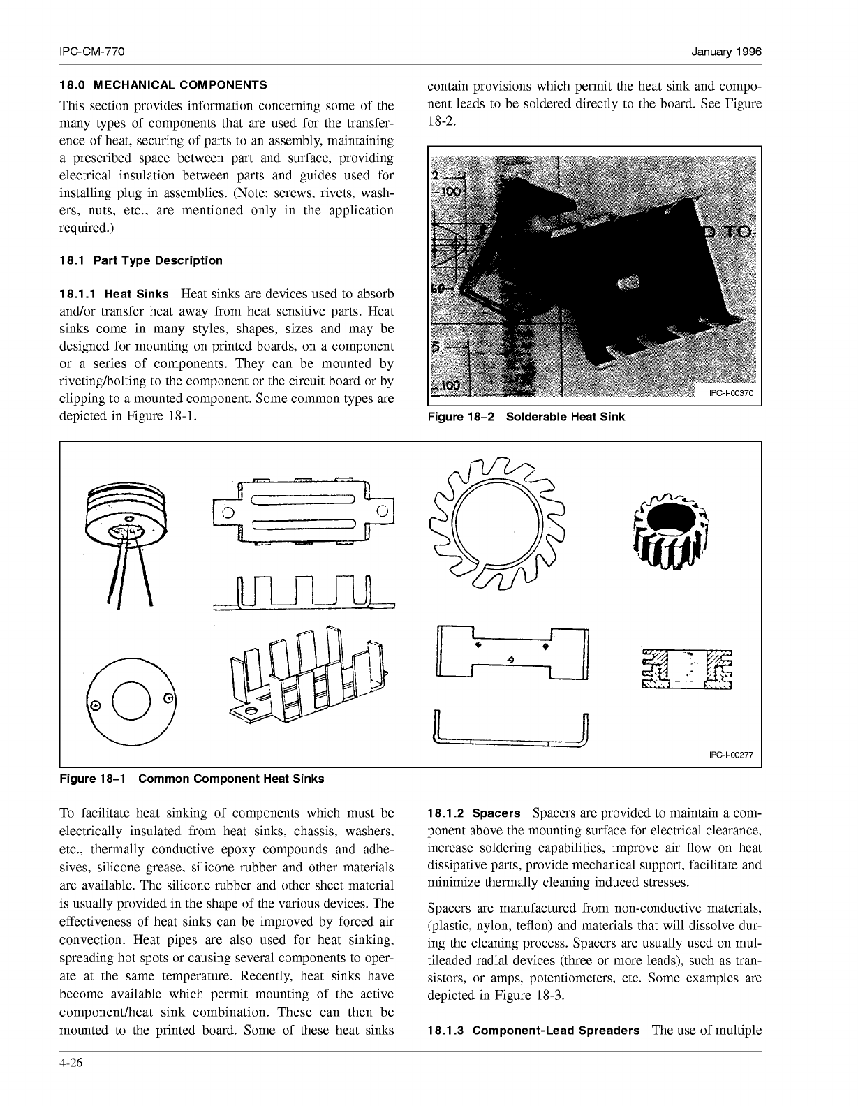
contain provisions which permit the heat sink and compo-
This section provides information concerning Some of the nent leads to be soldered directly to the board. See Figure
many types of components that are used for the transfer-
18-2.
ence of heat, securing of parts to an assembly, maintaining
a prescribed space between part and surface, providing
electrical insulation between parts and guides used for
installing plug in assemblies. (Note: screws, rivets, wash-
ers, nuts, etc., are mentioned only in the application
required.)
18.1 Part Type Description
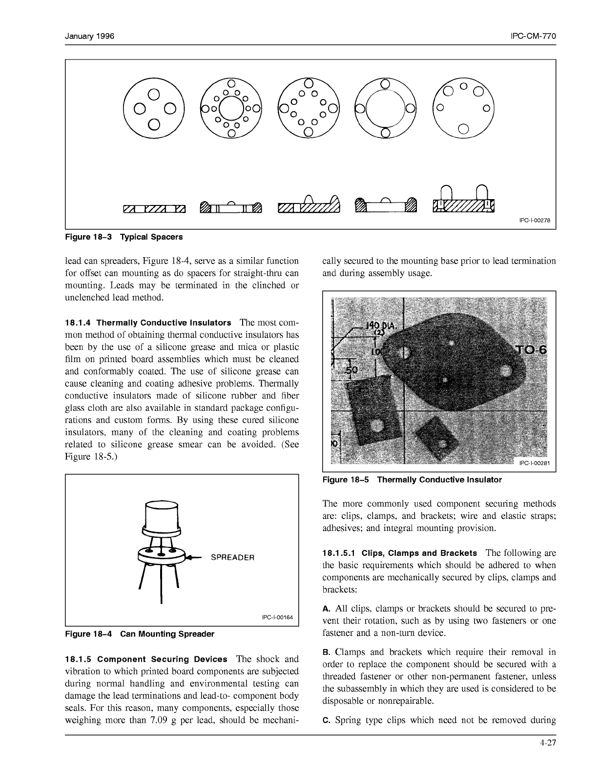
18.1.1 Heat Sinks
Heat sinks are devices used to absorb
and/or transfer heat away from heat sensitive parts. Heat
sinks come in many styles, shapes, sizes and may be
designed for mounting on printed boards, on a component
or a series of components. They can be mounted by
rivetingholting to the component or the circuit board or by
clipping to a mounted component. Some common types are
depicted in Figure
18-
1.
Figure 18-2 Solderable Heat Sink
I
1
n
o
*
n
U
I
I
U
9
IPC-1-00277
Figure 18-1 Common Component Heat Sinks
To facilitate heat sinking of components which must be
electrically insulated from heat sinks, chassis, washers,
etc., thermally conductive epoxy compounds and adhe-
sives, silicone grease, silicone rubber and other materials
are available. The silicone rubber and other sheet material
is usually provided in the shape of the various devices. The
effectiveness of heat sinks can be improved by forced air
convection. Heat pipes are also used for heat sinking,
spreading hot spots or causing several components to oper-
ate at the same temperature. Recently, heat sinks have
become available which permit mounting of the active
componentlheat sink combination. These can then be
mounted to the printed board. Some of these heat sinks
18.1.2 Spacers
Spacers are provided to maintain a com-
ponent above the mounting surface for electrical clearance,
increase soldering capabilities, improve air flow on heat
dissipative parts, provide mechanical support, facilitate and
minimize thermally cleaning induced stresses.
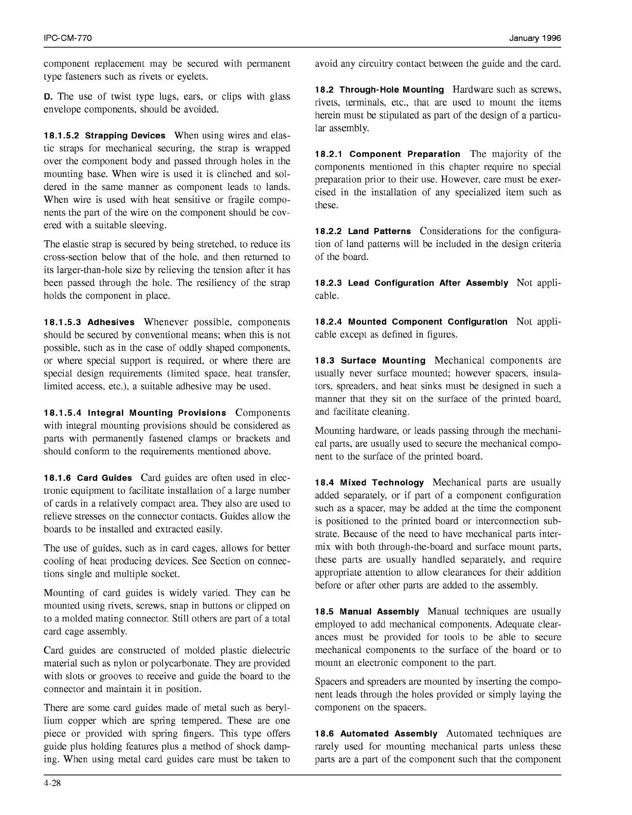
Spacers are manufactured from non-conductive materials,
(plastic, nylon, teflon) and materials that will dissolve dur-
ing the cleaning process. Spacers are usually used on mul-
tileaded radial devices (three or more leads), such as tran-
sistors, or amps, potentiometers, etc. Some examples are
depicted in Figure
18-3.
18.1.3 Component-Lead Spreaders
The use of multiple
4-26
COPYRIGHT Association Connecting Electronics Industries
Licensed by Information Handling Services
COPYRIGHT Association Connecting Electronics Industries
Licensed by Information Handling Services
January
1996
IPC-CM-770
@@O00
O
O0
o
O0
O
O
IPC-1-00278
Figure 18-3 Typical Spacers
lead can spreaders, Figure
18-4,
serve as a similar function
for offset can mounting as do spacers for straight-thru can
mounting. Leads may be terminated in the clinched or
unclenched lead method.
cally secured to the mounting base prior to lead termination
and during assembly usage.
I
18.1.4 Thermally Conductive Insulators
The most com-
mon method of obtaining thermal conductive insulators has
been by the use of a silicone grease and mica or plastic
film on printed board assemblies which must be cleaned
and conformably coated. The use of silicone grease can
cause cleaning and coating adhesive problems. Thermally
conductive insulators made of silicone rubber and fiber
glass cloth are also available in standard package configu-
rations and custom forms. By using these cured silicone
insulators, many of the cleaning and coating problems
related to silicone grease smear can be avoided. (See
Figure
18
-5
.)
Figure 18-5 Thermally Conductive Insulator
SPREADER
IPC-1-00164
I
L
Figure 18-4 Can Mounting Spreader
18.1.5 Component Securing Devices
The shock and
vibration to which printed board components are subjected
during normal handling and environmental testing can
damage the lead terminations and lead-to- component body
seals. For this reason, many components, especially those
weighing more than
7.09
g per lead, should be mechani-
The more commonly used component securing methods
are: clips, clamps, and brackets; wire and elastic straps;
adhesives; and integral mounting provision.
18.1 5.1 Clips, Clamps and Brackets
The following are
the basic requirements which should be adhered to when
components are mechanically secured by clips, clamps and
brackets:
A.
All clips, clamps or brackets should be secured to pre-
vent their rotation, such as by using two fasteners or one
fastener and a non-turn device.
B.
Clamps and brackets which require their removal in
order to replace the component should be secured with a
threaded fastener or other non-permanent fastener, unless
the subassembly in which they are used is considered to be
disposable or nonrepairable.
C.
Spring type clips which need not be removed during
4-21
COPYRIGHT Association Connecting Electronics Industries
Licensed by Information Handling Services
COPYRIGHT Association Connecting Electronics Industries
Licensed by Information Handling Services
IPC-CM-770
Januaty
1996
component replacement may be secured with permanent
type fasteners such as rivets or eyelets.
D.
The use of twist type lugs, ears, or clips with glass
envelope components, should be avoided.
18.1 5.2 Strapping Devices
When using wires and elas-
tic straps for mechanical securing, the strap is wrapped
over the component body and passed through holes in the
mounting base. When wire is used it is clinched and sol-
dered in the same manner as component leads to lands.
When wire is used with heat sensitive or fragile compo-
nents the part of the wire on the component should be cov-
ered with a suitable sleeving.
The elastic strap is secured by being stretched, to reduce its
cross-section below that of the hole, and then returned to
its larger-than-hole size by relieving the tension after it has
been passed through the hole. The resiliency of the strap
holds the component in place.
18.1 5.3 Adhesives
Whenever possible, components
should be secured by conventional means; when this is not
possible, such as in the case of oddly shaped components,
or where special support is required, or where there are
special design requirements (limited space, heat transfer,
limited access, etc.), a suitable adhesive may be used.
18.1.5.4 Integral Mounting Provisions
Components
with integral mounting provisions should be considered as
parts with permanently fastened clamps or brackets and
should conform to the requirements mentioned above.
18.1.6 Card Guides
Card guides are often used in elec-
tronic equipment to facilitate installation of a large number
of cards in a relatively compact area. They also are used to
relieve stresses on the connector contacts. Guides allow the
boards to be installed and extracted easily.
The use of guides, such as in card cages, allows for better
cooling of heat producing devices. See Section on connec-
tions single and multiple socket.
Mounting of card guides is widely varied. They can be
mounted using rivets, screws, snap in buttons or clipped on
to a molded mating connector. Still others are part of a total
card cage assembly.
Card guides are constructed of molded plastic dielectric
material such as nylon or polycarbonate. They are provided
with slots or grooves to receive and guide the board to the
connector and maintain it in position.
There are some card guides made of metal such as beryl-
lium copper which are spring tempered. These are one
piece or provided with spring fingers. This type offers
guide plus holding features plus a method of shock damp-
ing. When using metal card guides care must be taken to
avoid any circuitry contact between the guide and the card.
18.2 Through-Hole Mounting
Hardware such as screws,
rivets, terminals, etc., that are used to mount the items
herein must be stipulated as part of the design of a particu-
lar assembly.
18.2.1 Component Preparation
The majority of the
components mentioned in this chapter require no special
preparation prior to their use. However, care must be exer-
cised in the installation of any specialized item such as
these.
18.2.2 Land Patterns
Considerations for the configura-
tion of land patterns will be included in the design criteria
of the board.
18.2.3 Lead Configuration After Assembly
Not appli-
cable.
18.2.4 Mounted Component Configuration
Not appli-
cable except as defined in figures.
18.3 Surface Mounting
Mechanical components are
usually never surface mounted; however spacers, insula-
tors, spreaders, and heat sinks must be designed in such a
manner that they sit on the surface of the printed board,
and facilitate cleaning.
Mounting hardware, or leads passing through the mechani-
cal parts, are usually used to secure the mechanical compo-
nent to the surface of the printed board.
18.4 Mixed Technology
Mechanical parts are usually
added separately, or if part of a component configuration
such as a spacer, may be added at the time the component
is positioned to the printed board or interconnection sub-
strate. Because of the need to have mechanical parts inter-
mix with both through-the-board and surface mount parts,
these parts are usually handled separately, and require
appropriate attention to allow clearances for their addition
before or after other parts are added to the assembly.
18.5 Manual Assembly
Manual techniques are usually
employed to add mechanical components. Adequate clear-
ances must be provided for tools to be able to secure
mechanical components to the surface of the board or to
mount an electronic component to the part.
Spacers and spreaders are mounted by inserting the compo-
nent leads through the holes provided or simply laying the
component on the spacers.
18.6 Automated Assembly
Automated techniques are
rarely used for mounting mechanical parts unless these
parts are a part of the component such that the component
4-28
COPYRIGHT Association Connecting Electronics Industries
Licensed by Information Handling Services
COPYRIGHT Association Connecting Electronics Industries
Licensed by Information Handling Services