IPC-CM-770D-1996 - 第98页
IPC-CM-770 Januaty 1996 19.1.3 Metal-Core Boards Metal core boards or special printed board constructions are detailed in IPC-D-275. These types of products, due to their mechanical rigidity, make the component mounting …
January
1996
IPC-CM-770
and part are assembled automatically prior to placing on
the printed board.
18.7 Handling and Storage
The handling and storage of
mechanical components should be in accordance with the
guidelines of Section 26.
18.8 Soldering
Mechanical components or devices
described in this section are not normally soldered. How-
ever, soldering should be in accordance with
J-STD-001.
General soldering guidelines are discussed in Section 27.
18.9 Cleaning
The cleaning of assemblies utilizing items
such as spacers, spreaders and some insulators must be
performed with great care to insure that the fluxes used are
removed in accordance with the end item equipment class
requirements and have no deleterious effect on the
assembly.
Devices utilizing thermally conductive insulators which
have had silicone grease applied can create cleaning and
conformal coating problems. Cleaning must be performed
using techniques that provide proper cleaning without caus-
ing the silicone grease to spread and contaminate other
areas of the assembly. Improper cleaning may also wash
the silicone grease away. General cleaning guidelines are
discussed in Section 28.
18.1
O
Conformal Coating
See Section 29 conformal
coating. Any special requirements must be considered dur-
ing the design of a particular assembly and included in the
design documentation.
19.0 PACKAGING AND INTERCONNECTING
STRUCTURES
Many different board types can be used to mount inter-
mixed assemblies. As stated earlier boards may be single,
double or multilayered. The material used to manufacture
the printed board, or printed board structure many times
plays a large role in the component mounting techniques
that may be used to place parts on the printed board struc-
ture or board. Rigid printed board design is detailed in
IPC-D-275 for single- and double-sided boards and for
multilayer printed boards.
If
flexible printed boards are
used for mounting components, the design aspects of
single- and double-sided boards are detailed in IPC-D-249.
19.1 Printed Boards
There are three basic types of
printed circuit (printed wiring) boards, all of which can be
manufactured in both “rigid” and flexible materials. They
are listed below in ascending order of interconnection wir-
ing and component density:
Single-Sided-With conductors on only one surface of a
dielectric (insulating) base.
Double-Sided-With conductors on both sides of a
dielectric base that are usually interconnected by plated-
through or otherwise reinforced holes.
Multilayer-Boards with three or more conductor layers
separated by dielectric material and usually intercon-
nected by plated-through interlayer holes.
The least expensive type of board, single sided, is used for
relatively unsophisticated circuitry, and they are applicable
when circuit types and circuit speeds do not demand
unusual electrical characteristics. The more expensive,
double sided type of board is required for more complex,
more dense circuit types requiring interconnecting layers.
The requirements for high speed circuits in computer and
space industries, with a requirement for a still further
increase in package density, has lead to the demand for the
most expensive type of board, multilayer.
All printed boards have an insulating base often referred to
as the dielectric or laminate. Laminate bases for single-
sided, double-sided or multilayer printed boards can be
either “rigid” or “flexible.”
The most common laminate bases for rigid printed boards
are:
Phenolic-resin-impregnated paper (commonly called
paper-phenolic)
Acrylic-polyester-impregnated random glass mat
Epoxy-impregnated paper
Epoxy-impregnated fiberglass cloth (commonly called
glass-epoxy)
19.1.1 Rigid Laminate Boards
“Rigid” laminate materi-
als are selected according to physical, thermal and electri-
cal requirements. The first three materials listed above are
punchable, enabling low-cost hole formation, making them
popular for single-sided board use. However, their dimen-
sional stability is unsuitable for making plated-through-
hole boards. The more expensive glass-epoxy laminates
have good dimensional stability, usually making them the
choice for plated-through- hole, double-sided and multi-
layer boards. Glass-epoxy is not as punchable as the other
laminate types
so
that holes are usually drilled. Other lami-
nate types are available for high temperature, high fre-
quency and other special requirements.
19.1.2 Flexible Laminate Boards
When flexible printed
board types are used for surface mounting or through-the-
board mounting or intermixed assemblies, the component
mounting task may become more difficult, depending on
how the detailed assembly is structured. Usually, stiffeners
or other rigid sections of the flexible board are provided to
insure proper surface for the component mounting. In addi-
tion flexible printed boards usually take many different
shapes and special fixturing may be required in order for
the component assembly equipment to adequately mount
and attach electronic parts.
4-29
COPYRIGHT Association Connecting Electronics Industries
Licensed by Information Handling Services
COPYRIGHT Association Connecting Electronics Industries
Licensed by Information Handling Services
IPC-CM-770
Januaty
1996
19.1.3 Metal-Core Boards
Metal core boards or special
printed board constructions are detailed in IPC-D-275.
These types of products, due to their mechanical rigidity,
make the component mounting task somewhat easier. How-
ever, the thermal characteristics of the interconnection
structure require that the soldering or attachment technique
consider the impact that the thermal mass has on the solder
joint solidification.
19.2 Surface Mounting
Surface mounting techniques are
applicable to any type of board or substrate material. How-
ever, when using leadless components, the differing coeffi-
cients of expansion between the component and the sub-
strate must be considered.
Surface mounting is suitable for single sided, double sided
(with or without plated-through-holes), and multilayer
boards. Mounting techniques are independent of board
type.
Techniques which have been developed to minimize the
thermal expansion problem have included the development
of special board types with controlled expansion coeffi-
cients. These include ceramic boards, conventional epoxy-
glass and polyimide- glass boards, and special laminates
such as invar or copper substrate clad with epoxy-glass on
each side. Proper selection of material types and thick-
nesses permits tailoring the thermal expansion coefficients
to any desired value.
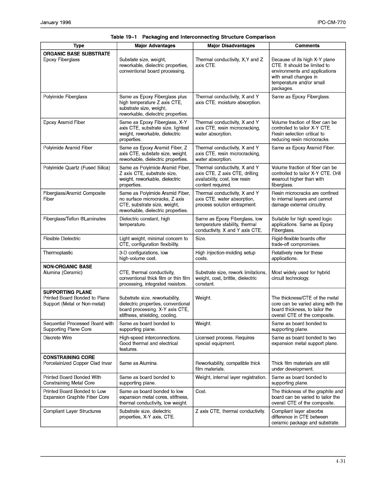
Table 19-1 provides a comparison of the advantages and
disadvantages of many of the available printed board
structures.
19.3 Supporting-Plane Printed Board Structures
sup-
porting metallic or non-metallic planes can be used with
conventional printed boards or with customer processing to
enhance printed board properties. Depending on the results
desired, the supporting plane can be electrically functional
or not and can also serve as a structure stiffener, heatsink
and/or CTE constraint.
I
n
I
Circuil
panern
Chip
carrier
I I
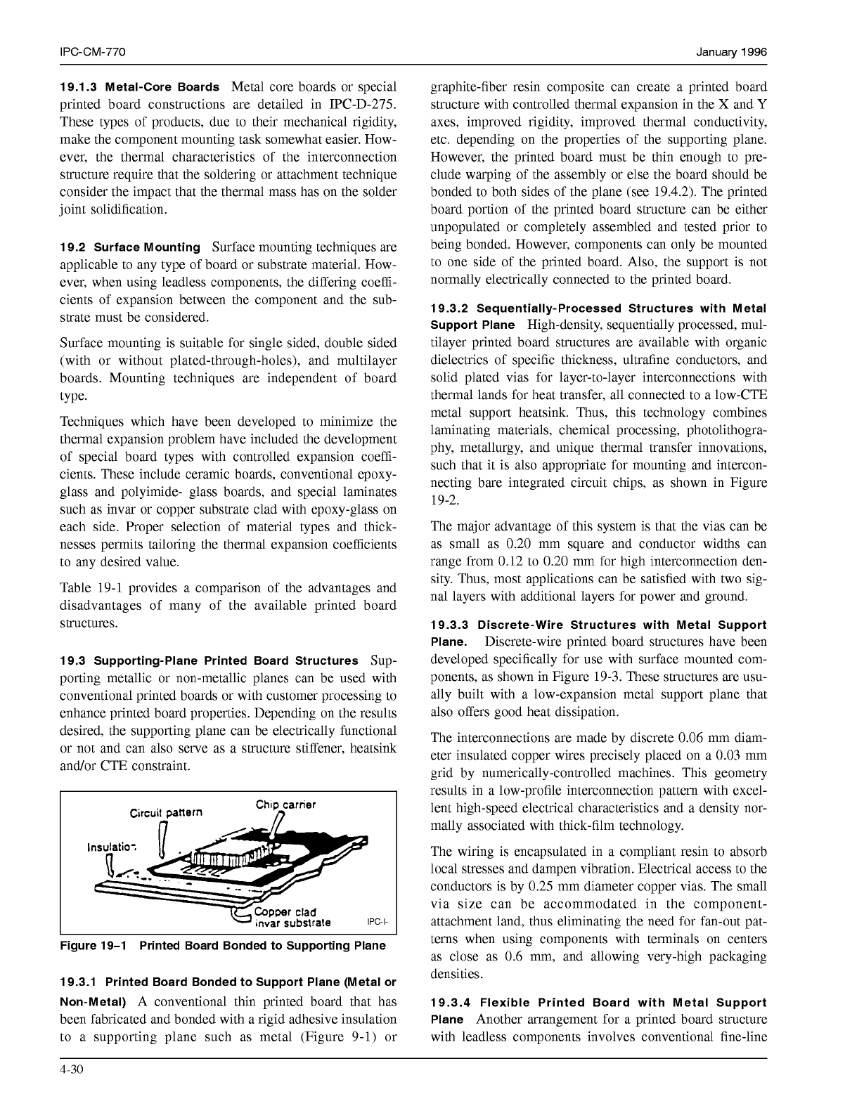
Figure 19-1 Printed Board Bonded to Supporting Plane
19.3.1 Printed Board Bonded to Support Plane (Metal or
Non-Metal)
A conventional thin printed board that has
been fabricated and bonded with a rigid adhesive insulation
to a supporting plane such as metal (Figure 9-1) or
graphite-fiber resin composite can create a printed board
structure with controlled thermal expansion in the
X
and
Y
axes, improved rigidity, improved thermal conductivity,
etc. depending on the properties of the supporting plane.
However, the printed board must be thin enough to pre-
clude warping of the assembly or else the board should be
bonded to both sides of the plane (see 19.4.2). The printed
board portion of the printed board structure can be either
unpopulated or completely assembled and tested prior to
being bonded. However, components can only be mounted
to one side of the printed board. Also, the support is not
normally electrically connected to the printed board.
19.3.2 Sequentially-Processed Structures with Metal
Support Plane
High-density, sequentially processed, mul-
tilayer printed board structures are available with organic
dielectrics of specific thickness, ultrafine conductors, and
solid plated vias for layer-to-layer interconnections with
thermal lands for heat transfer, all connected to a low-CTE
metal support heatsink. Thus, this technology combines
laminating materials, chemical processing, photolithogra-
phy, metallurgy, and unique thermal transfer innovations,
such that it is also appropriate for mounting and intercon-
necting bare integrated circuit chips, as shown in Figure
19-2.
The major advantage of this system is that the vias can be
as small as 0.20 mm square and conductor widths can
range from 0.12 to 0.20 mm for high interconnection den-
sity. Thus, most applications can be satisfied with two sig-
nal layers with additional layers for power and ground.
19.3.3 Discrete-Wire Structures with Metal Support
Plane.
Discrete-wire printed board structures have been
developed specifically for use with surface mounted com-
ponents, as shown in Figure 19-3. These structures are usu-
ally built with a low-expansion metal support plane that
also offers good heat dissipation.
The interconnections are made by discrete
0.06
mm diam-
eter insulated copper wires precisely placed on a 0.03 mm
grid by numerically-controlled machines. This geometry
results in a low-profile interconnection pattern with excel-
lent high-speed electrical characteristics and a density nor-
mally associated with thick-film technology.
The wiring is encapsulated in a compliant resin to absorb
local stresses and dampen vibration. Electrical access to the
conductors is by 0.25 mm diameter copper vias. The small
via size can be accommodated in the component-
attachment land, thus eliminating the need for fan-out pat-
terns when using components with terminals on centers
as close as
0.6
mm, and allowing very-high packaging
densities.
19.3.4 Flexible Printed Board with Metal Support
Plane
Another arrangement for a printed board structure
with leadless components involves conventional fine-line
4-30
COPYRIGHT Association Connecting Electronics Industries
Licensed by Information Handling Services
COPYRIGHT Association Connecting Electronics Industries
Licensed by Information Handling Services
January
1996
IPC-CM-770
Table
19-1
Packaging and Interconnecting Structure Comparison
ORGANIC BASE SUBSTRATE
Epoxy Fiberglass
Polyimide Fiberglass
Epoxy Aramid Fiber
Polyimide Aramid Fiber
Polyimide Quartz (Fused Silica)
Fiberglass/Aramid Composite
Fiber
Fiberglass/Teflon @Laminates
Flexible Dielectric
Thermoplastic
NON-ORGANIC BASE
Alumina (Ceramic)
SUPPORTING PLANE
Printed Board Bonded to Plane
Support (Metal or Non-metal)
Sequential Processed Board with
Supporting Plane Core
Discrete Wire
CONSTRAINING CORE
Porcelainized Copper Clad Invar
Printed Board Bonded With
Constraining Metal Core
Printed Board Bonded to Low
Expansion Graphite Fiber Core
Compliant Layer Structures
Major Advantages
Substate size, weight,
reworkable, dielectric properties,
conventional board processing.
Same as Epoxy Fiberglass plus
high temperature
Z
axis CTE,
substrate size, weight,
reworkable, dielectric properties.
Same as Epoxy Fiberglass, X-Y
axis CTE, substrate size, lightest
weight, reworkable, dielectric
properties.
Same as Epoxy Aramid Fiber,
Z
axis CTE, substate size, weight,
reworkable, dielectric properties.
Same as Polyimide Aramid Fiber,
Z
axis CTE, substrate size,
weight, reworkable, dielectric
properties.
Same as Polyimide Aramid Fiber,
no surface microcracks,
Z
axis
CTE, substrate size, weight,
reworkable, dielectric properties.
Dielectric constant, high
temperature.
Light weight, minimal concern to
CTE, configuration flexibility.
3-D configurations, low
high-volume cost.
CTE, thermal conductivity,
conventional thick film or thin film
processing, integrated resistors.
Substrate size, reworkability,
dielectric properties, conventional
board processing. X-Y axis CTE,
stiffness, shielding, cooling.
Same as board bonded to
supporting plane.
High-speed interconnections.
Good thermal and electrical
features.
Same as Alumina.
Same as board bonded to
supporting plane.
Same as board bonded to low
expansion metal cores, stiffness,
thermal conductivity, low weight.
Substrate size, dielectric
properties, X-Y axis, CTE.
Major Disadvantages
Because of its high X-Y plane Thermal conductivity, X,Y and
Z
Comments
axis CTE. CTE. It should be limited to
environments and applications
with small changes in
temperature and/or small
packages.
Thermal conductivity, X and Y
axis CTE, moisture absorption.
Same as Epoxy Fiberglass.
Thermal conductivity, X and Y
Resin selection critical to water absorption.
controlled to tailor X-Y CTE. axis CTE, resin microcracking,
Volume fraction of fiber can be
reducing resin microcracks.
Thermal conductivity, X and Y Same as Epoxy Aramid Fiber.
axis CTE, resin microcracking,
water absorption.
Thermal conductivity, X and Y Volume fraction of fiber can be
axis CTE,
Z
axis CTE, drilling controlled to tailor X-Y CTE. Drill
availability, cost, low resin wearout higher than with
content required.
fiberglass.
Thermal conductivity, X and Y Resin microcracks are confined
axis CTE, water absorption, to internal layers and cannot
process solution entrapment.
damage external circuitry.
Same as Epoxy Fiberglass, low Suitable for high speed logic
temperature stability, thermal applications. Same as Epoxy
conductivity. X and Y axis CTE.
Fiberglass.
Size. Rigid-flexible boards offer
High injection-molding setup Relatively new for these
trade-off compromises.
costs.
applications.
Substrate size, rework limitations,
circuit technology. weight, cost, brittle, dielectric
Most widely used for hybrid
constant.
Weight.
The thickness/CTE of the metal
core can be varied along with the
board thickness, to tailor the
overall CTE of the composite.
supporting plane.
Weight.
expansion metal support plane. special equipment.
Same as board bonded to two
Licensed process. Requires
Same as board bonded to
Reworkability, compatible thick
Same as board bonded to Weight, internal layer registration.
under development. film materials.
Thick film materials are still
supporting plane.
board can be varied to tailor the
overall CTE of the composite.
difference in CTE between
ceramic package and substrate.
Cost. The thickness of the graphite and
Z
axis CTE, thermal conductivity. Compliant layer absorbs
4-3
1
COPYRIGHT Association Connecting Electronics Industries
Licensed by Information Handling Services
COPYRIGHT Association Connecting Electronics Industries
Licensed by Information Handling Services