00198377-01_SM_JTF-ML2_en.pdf - 第20页
2 General Tasks 2.1 Hardware Tasks 20 Service Manual SIPLACE JTF-ML2 08/2017 ► Pull the conveyor out. ► Loosen the screw (2) at conveyor pivot (1) . ► (3) Push the conveyor pivot until end position away from the tower. ►…
2 General Tasks
2.1 Hardware Tasks
Service Manual SIPLACE JTF-ML2 08/2017 19
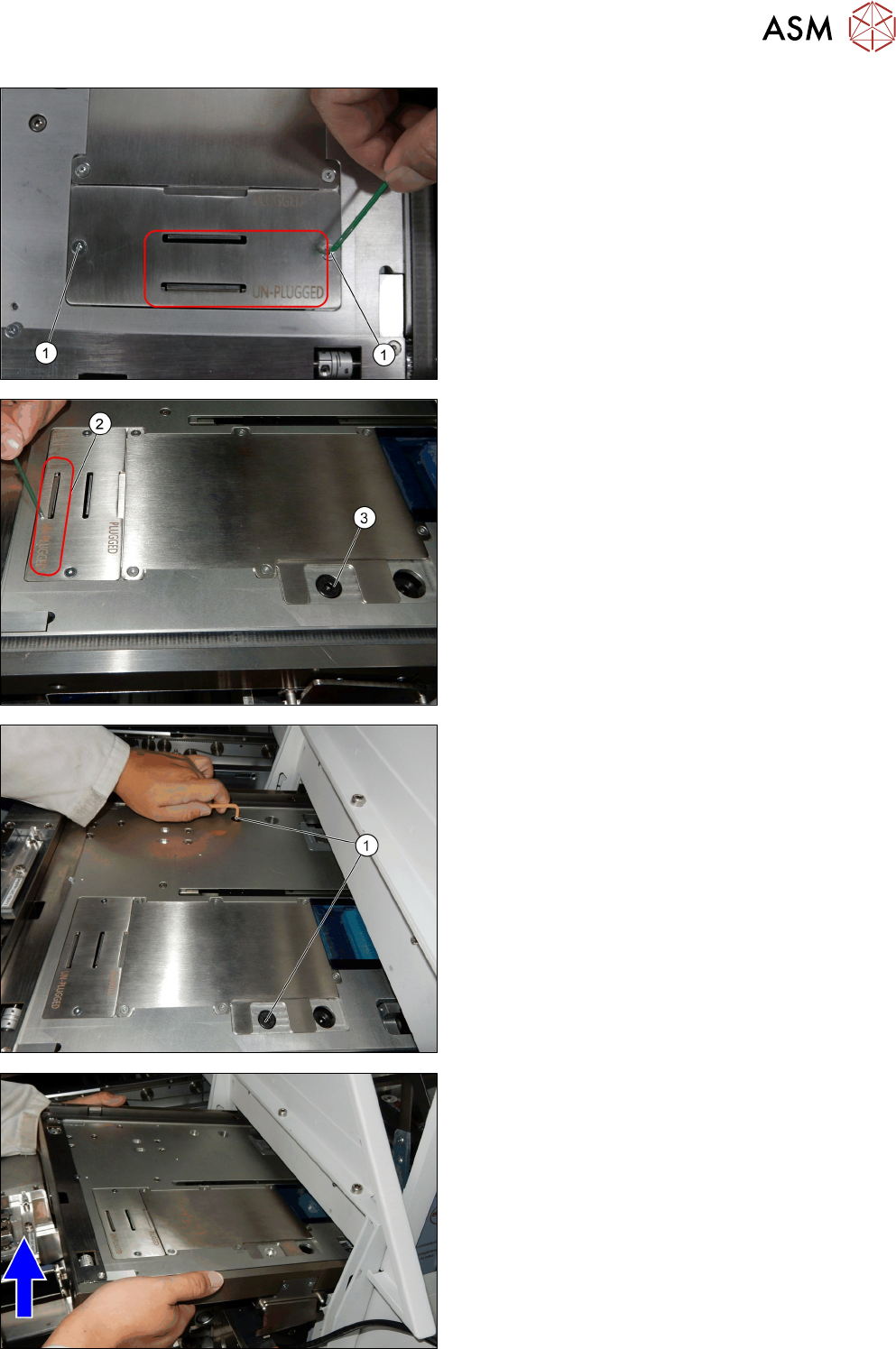
► Reinsert the PCBA position Cover [03148885-xx]
in the unplugged position.
► Fix the two screws ISO 10642 - M3x6-A2-70
[03082814-xx] (1).
The cover now stays in the unplugged position (2).
The screw ISO 7379 - 8 x 16-12.9 [03005644-xx] (3) is
accessible.
► Remove the two screws ISO 7379 - 8 x 16-12.9
[03005644-xx] (1).
► Lift the conveyor a bit up on the side towards the
machine. Lift the conveyor until it clears the bot-
tom slide guide.
2 General Tasks
2.1 Hardware Tasks
20 Service Manual SIPLACE JTF-ML2 08/2017
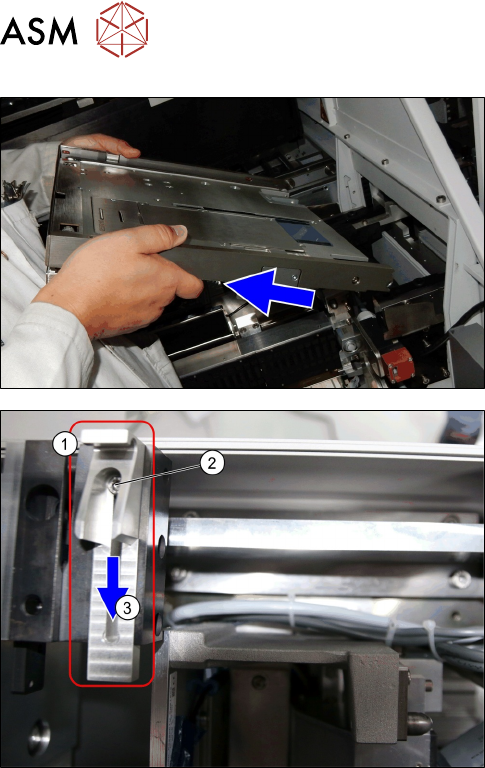
► Pull the conveyor out.
► Loosen the screw (2) at conveyor pivot (1).
► (3) Push the conveyor pivot until end position
away from the tower.
► Fasten the screw (2) at conveyor pivot (1).
Installation
► Follow the removal instructions in reverse order for installation (See also 2.1.6 "Mounting the
Conveyor" [}29]).
► Extent or retract the conveyor pivot.
2 General Tasks
2.1 Hardware Tasks
Service Manual SIPLACE JTF-ML2 08/2017 21
2.1.2 Removing Tower from Machine
Parts, Equipment and Tools
●
Standard tools
Removal
► Switch off the machine, disconnect it from the power supply and secure it to prevent
unauthorized reactivation. Observe the instructions in section 1.2 "Preparatory Work..." [}11].
NOTICE
Cassettes
Make sure all cassettes are removed from the tower before powering down.
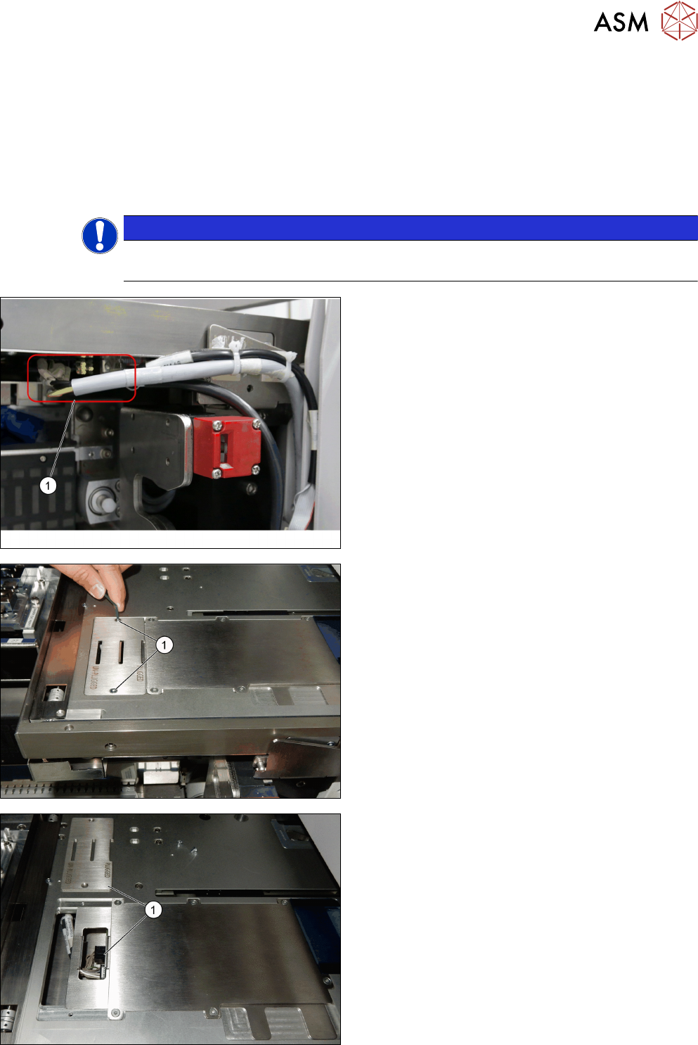
► Unplug the cables from the connectors X2.COTI1
and X4.COTI1 in the conveyor base of the
SIPLACE JTF-ML2 (1).
► Remove the two screws ISO 10642 - M3x6-
A2-70 [03082814-xx] (1).
► Remove the PCBA position Cover [03148885-xx]
(1).