00198377-01_SM_JTF-ML2_en.pdf - 第23页
2 General Tasks 2.1 Hardware Tasks Service Manual SIPLACE JTF-ML2 08/2017 23 The cover now stays in the unplugged position (2) . One of the two screws ISO 7379 - 10 x 25-12.9 [03005652-xx] (3) is accessible. ► Remove the…
2 General Tasks
2.1 Hardware Tasks
22 Service Manual SIPLACE JTF-ML2 08/2017
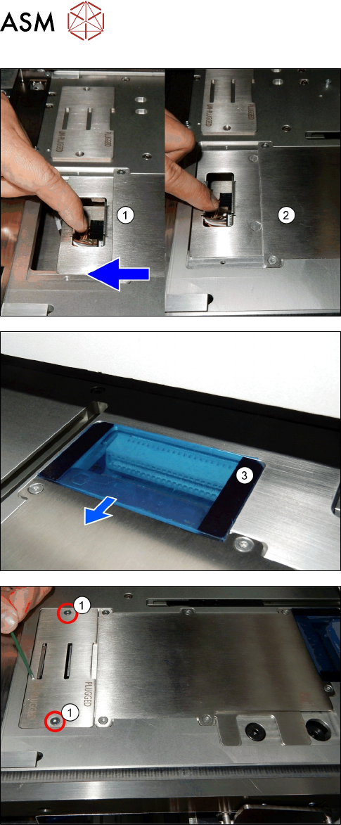
► Pull the PCB mounting part [03138496-xx] (1) to-
wards the machine.
ð The PCB mounting part [03138496-xx]
changes from plugged to unplugged position
(2).
The power is disconnected (3).
► Reinsert the PCBA position Cover [03148885-xx].
► Fix the two screws ISO 10642 - M3x6-A2-70
[03082814-xx] (1).
2 General Tasks
2.1 Hardware Tasks
Service Manual SIPLACE JTF-ML2 08/2017 23
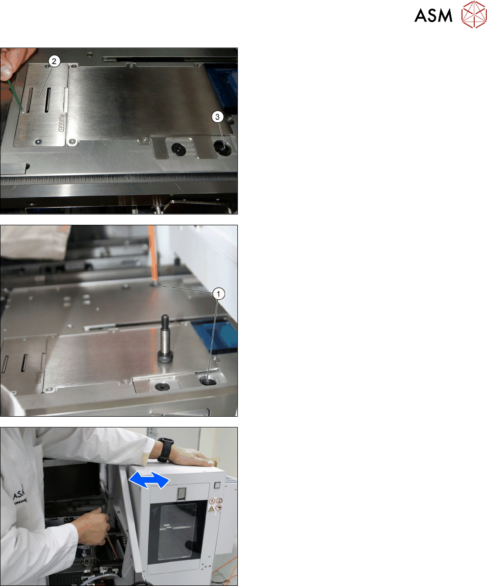
The cover now stays in the unplugged position (2).
One of the two screws ISO 7379 - 10 x 25-12.9
[03005652-xx] (3) is accessible.
► Remove the two screws ISO 7379 - 10 x 25-12.9
[03005652-xx] (1).
► Move the tower a bit while removing the screws
to reduce pressure on the screws.
2 General Tasks
2.1 Hardware Tasks
24 Service Manual SIPLACE JTF-ML2 08/2017
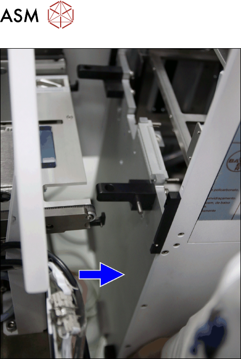
► Grab the tower with one hand at the handle on
the bottom and the other hand on top of the
tower.
► Pull the Tower carefully parallel from the slidings
out of the machine.
Installation
► Follow the removal instructions in reverse order for installation (See also 2.1.5 "Mounting the
Tower" [}27]).