00198377-01_SM_JTF-ML2_en.pdf - 第42页
3 Tower Mechanics 3.3 Replacing the Lifting Motor 42 Service Manual SIPLACE JTF-ML2 08/2017 Lifting motor w/ pulley [03133230-xx] Installation ► Follow the removal instructions in reverse order for installation. Also obs…
3 Tower Mechanics
3.3 Replacing the Lifting Motor
Service Manual SIPLACE JTF-ML2 08/2017 41
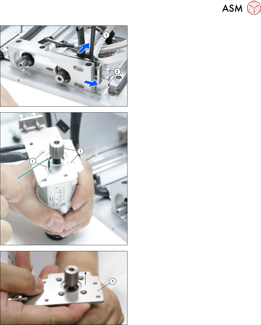
► Make sure the two screws ISO 4762 - M 4 x 12-
A2-70 [03042553-xx] (2) are proper loosened on
the Lifting Motor Flange Holder.
► Remove the locking screws.
► Pull the BLDC motor BG42x30 w/ brake/encoder
[03129247-xx] (1) with the Lifting Motor Flange
Holder [03130994-xx] out of the Lifting fixed
Bearing Support [03134808-xx].
► Remove the four screws ISO 10642 - M3x8-
A2-70 [03082815-xx] (1) from the Lifting Motor
Flange Holder [03130994-xx].
► Remove the Lifting Motor Flange Holder
[03130994-xx] (1) from the Lifting motor w/ pulley
[03133230-xx].
► Take note of orientation of the motor.
3 Tower Mechanics
3.3 Replacing the Lifting Motor
42 Service Manual SIPLACE JTF-ML2 08/2017
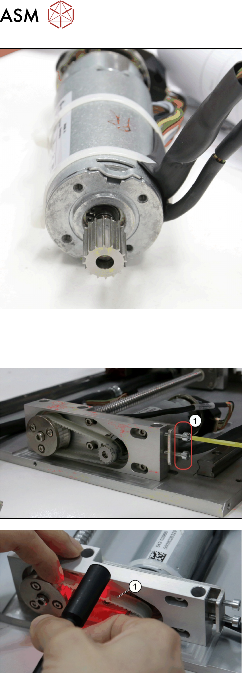
Lifting motor w/ pulley [03133230-xx]
Installation
► Follow the removal instructions in reverse order for installation. Also observe the following in-
structions:
► Adjust the tension by turning the two screws ISO
4762 - M 4 x 12-A2-70 [03042553-xx] (1) to
225±15 HZ.
► Check the belt tension (1) with the help of a belt
tension measuring device.
► Follow the instructions Mounting the Tower.
3 Tower Mechanics
3.4 Replacing the Ball Screw
Service Manual SIPLACE JTF-ML2 08/2017 43
3.4 Replacing the Ball Screw
Parts, Equipment and Tools
●
Standard tools
●
Ball screw FSB type [03134730-xx]
Removal
► Switch off the machine, disconnect it from the power supply and secure it to prevent
unauthorized reactivation. Observe the instructions in section 1.2 "Preparatory Work..." [}11].
► Remove the tower from the machine (See 2.1.2 "Removing Tower from Machine" [}21]).
► Remove the top cover (see 2.1.3 "Removing Tower Top Cover" [}25]).
► Remove the side cover (see 2.1.4 "Removing Side Cover" [}27]).
► Remove the Synchronized Pulley AT3 z=32 [03129152-xx] as shown in 3.1 "Replacing the
Synchronized Pulley" [}35].
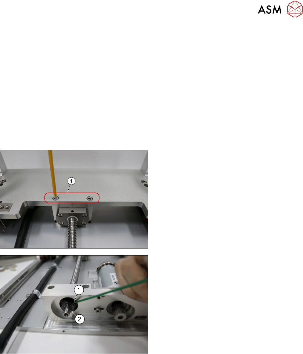
► Remove the screws (1).
► Remove stud screw (1) from the Bearing Lock
Nut M10x1 [03134432-xx] (2)