00198377-01_SM_JTF-ML2_en.pdf - 第53页
3 Tower Mechanics 3.9 Replacing the Door Lock Stop Block Service Manual SIPLACE JTF-ML2 08/2017 53 Installation ► Follow the removal instructions in reverse order for installation. 3.9 Replacing the Door Lock Stop Block …
3 Tower Mechanics
3.8 Replacing the Door Guide Strip
52 Service Manual SIPLACE JTF-ML2 08/2017
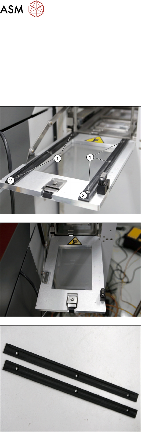
3.8 Replacing the Door Guide Strip
Parts, Equipment and Tools
●
Standard tools
●
Door guide strip [03133492-xx]
Removal
► Switch off the machine, disconnect it from the power supply and secure it to prevent
unauthorized reactivation. Observe the instructions in section 1.2 "Preparatory Work..." [}11].
In case remove the tower from the machine (see 2.1.2 "Removing Tower from Machine" [}21])
► Open the door.
► Remove the six screws DIN EN ISO 7380-M3 x 6-
A2-70 [03045194-xx] (1).
► Remove the two Door guide strips [03133492-xx] (2).
Door without Door guide strips [03133492-xx].
Door guide strips [03133492-xx]
3 Tower Mechanics
3.9 Replacing the Door Lock Stop Block
Service Manual SIPLACE JTF-ML2 08/2017 53
Installation
► Follow the removal instructions in reverse order for installation.
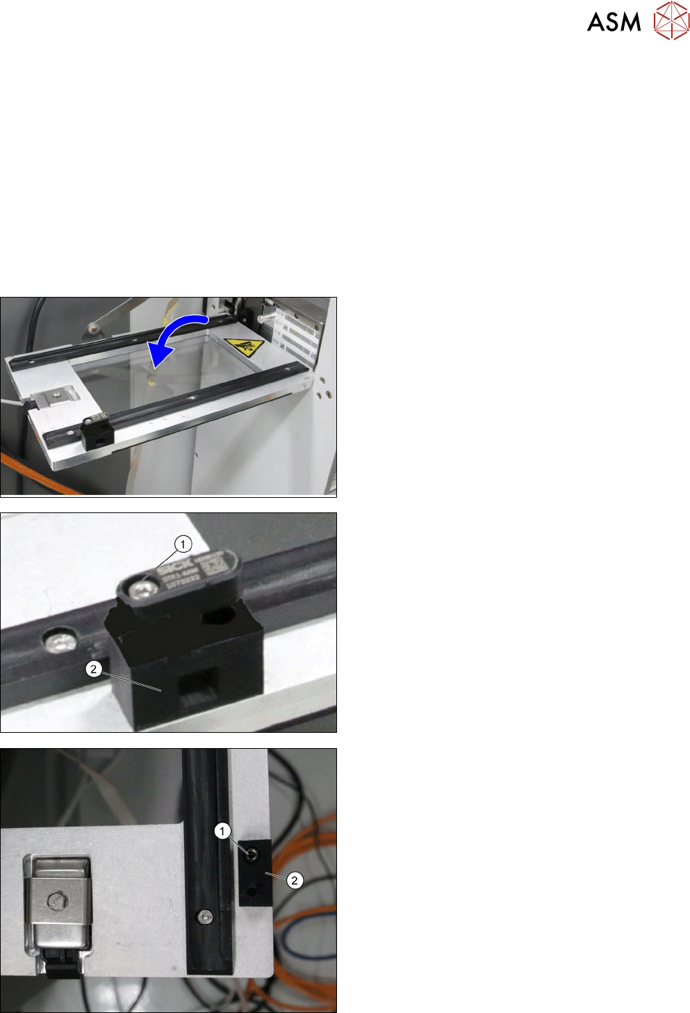
3.9 Replacing the Door Lock Stop Block
Parts, Equipment and Tools
●
Standard tools
●
Door lock stop block [03145840-xx]
Removal
► Switch off the machine, disconnect it from the power supply and secure it to prevent
unauthorized reactivation. Observe the instructions in section 1.2 "Preparatory Work..." [}11].
► Open the door.
► Remove the screw ISO 4762 - M 3 x 20-A2-70
[03042547-xx] (1).
► Remove the Transponder safety switch STR1 ac-
tuator (part of door safety switch [03158838-xx])
(2).
► Remove screw DIN EN ISO 7380-M3 x 6-A2-70
[03045194-xx] (1).
► Remove Door lock stop block [03145840-xx] (2).
3 Tower Mechanics
3.10 Replacing the Tray Guide
54 Service Manual SIPLACE JTF-ML2 08/2017
Installation
► Follow the removal instructions in reverse order for installation.
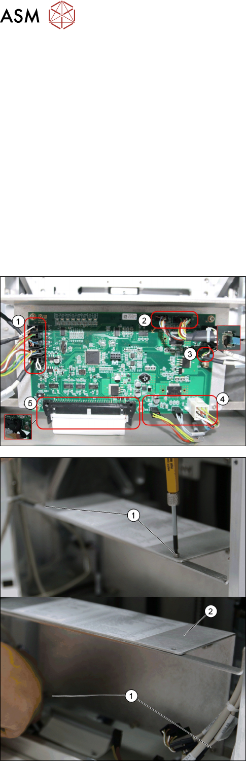
3.10 Replacing the Tray Guide
Parts, Equipment and Tools
●
Standard tools
●
Tray guide [03133351-xx]
Removal
► Switch off the machine, disconnect it from the power supply and secure it to prevent
unauthorized reactivation. Observe the instructions in section 1.2 "Preparatory Work..." [}11].
► Remove the cassette from the tower (see 6.3 "Remove the Cassette from the SIPLACE JTF-
ML2" [}144]).
► Remove the tower from the machine (see 2.1.2 "Removing Tower from Machine" [}21])
► Remove the top cover (see 2.1.3 "Removing Tower Top Cover" [}25]).
► Remove all cables from the PCBA, JFT-ML2 con-
trol board [03125534-xx].
1. X22; X8; X7; X6; X5
2. X16; X15
3. X23
4. X18; X19; X17
5. X4
► Remove the four screws ISO 4762 - M 3 x 6-
A2-70 [03042541-xx] (1).
► Remove the Plate f. PCBA Support [03129139-
xx] (2).