00198377-01_SM_JTF-ML2_en.pdf - 第64页
3 Tower Mechanics 3.13 Removing the Dual Kicker and Dismantling Parts 64 Service Manual SIPLACE JTF-ML2 08/2017 ► Remove the Remove the dowel pin ISO 2338 - 3h8 x 20-A1 [03080832-xx] (1) . ► Remove the Pusher lever v2 L=…
3 Tower Mechanics
3.13 Removing the Dual Kicker and Dismantling Parts
Service Manual SIPLACE JTF-ML2 08/2017 63
3.13.4 Replacing the Motor Sub-Assembly
Parts, Equipment and Tools
●
Standard tools
●
Motor sub-assembly [03156525-xx]
Removal
► Switch off the machine, disconnect it from the power supply and secure it to prevent
unauthorized reactivation. Observe the instructions in section 1.2 "Preparatory Work..." [}11].
► Remove the tower from the machine (see 2.1.2 "Removing Tower from Machine" [}21])
► Remove the top cover (see 2.1.3 "Removing Tower Top Cover" [}25]).
► Remove the Dual Kicker from the tower (see 3.13 "Removing the Dual Kicker and Dismantling
Parts" [}57])
► Remove the belt from the kicker (see 3.13.3 "Replacing the Dual Kicker Timing Belt" [}62]).
► Remove the Urethane Bumber (see 3.5 "Replacing the Urethane Bumpers" [}46]).
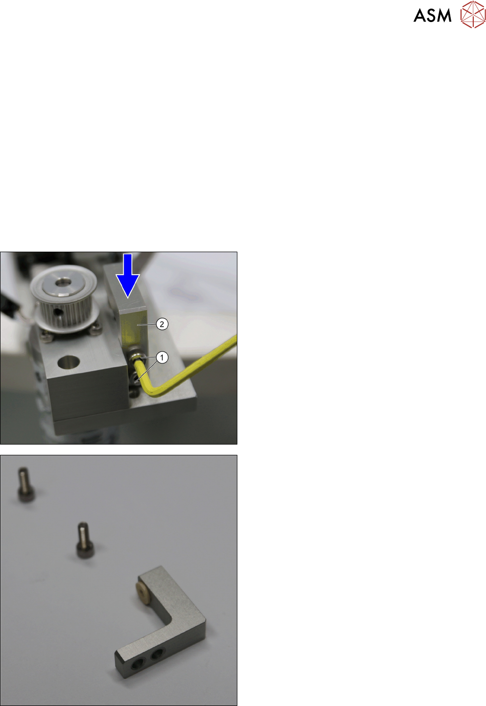
► Remove the two screws ISO 4762 - M 4 x 12-
A2-70 [03042553-xx] (1) from the Bushing Holder
top v2 [03155358-xx] (2).
► Remove the Bushing Holder top v2 [03155358-
xx] (2).
Bushing Holder top v2 [03155358-xx]
3 Tower Mechanics
3.13 Removing the Dual Kicker and Dismantling Parts
64 Service Manual SIPLACE JTF-ML2 08/2017
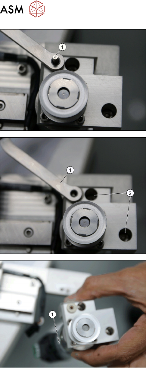
► Remove the Remove the dowel pin ISO 2338 -
3h8 x 20-A1 [03080832-xx] (1).
► Remove the Pusher lever v2 L=65 [03155364-xx]
(1).
► Remove the two screws ISO 4762 - M 4 x 12-
A2-70 [03042553-xx] (2).
► Remove the Motor Sub- Assembly
[03156525-xx] (1).
3 Tower Mechanics
3.13 Removing the Dual Kicker and Dismantling Parts
Service Manual SIPLACE JTF-ML2 08/2017 65
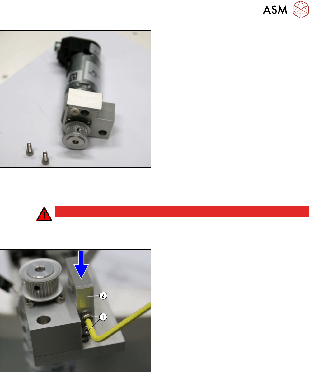
Motor Sub- Assembly [03156525-xx]
Installation
► Follow the removal instructions in reverse order for installation. Also observe the following
steps:
DANGER
Danger of a crash
If there is a gap between the bushing holder and the belt kicker mounting, the bushing
holder could move.
► While fixing the two screws ISO 4762 - M 4 x 12-
A2-70 [03042553-xx] (1), press the Bushing
Holder top v2 [03155358-xx] (2) down.