00198377-01_SM_JTF-ML2_en.pdf - 第70页
4 Conveyor Mechanics 4.1 Replacing the Fitting Screw [03005652-xx] 70 Service Manual SIPLACE JTF-ML2 08/2017 ► Remove the two screws ISO 10642 - M3x6- A2-70 [03082814-xx] (1) . ► Remove the PCBA position Cover [03148885-…
4 Conveyor Mechanics
4.1 Replacing the Fitting Screw [03005652-xx]
Service Manual SIPLACE JTF-ML2 08/2017 69
4 Conveyor Mechanics
4.1 Replacing the Fitting Screw [03005652-xx]
Parts, Equipment and Tools
●
Standard tools
●
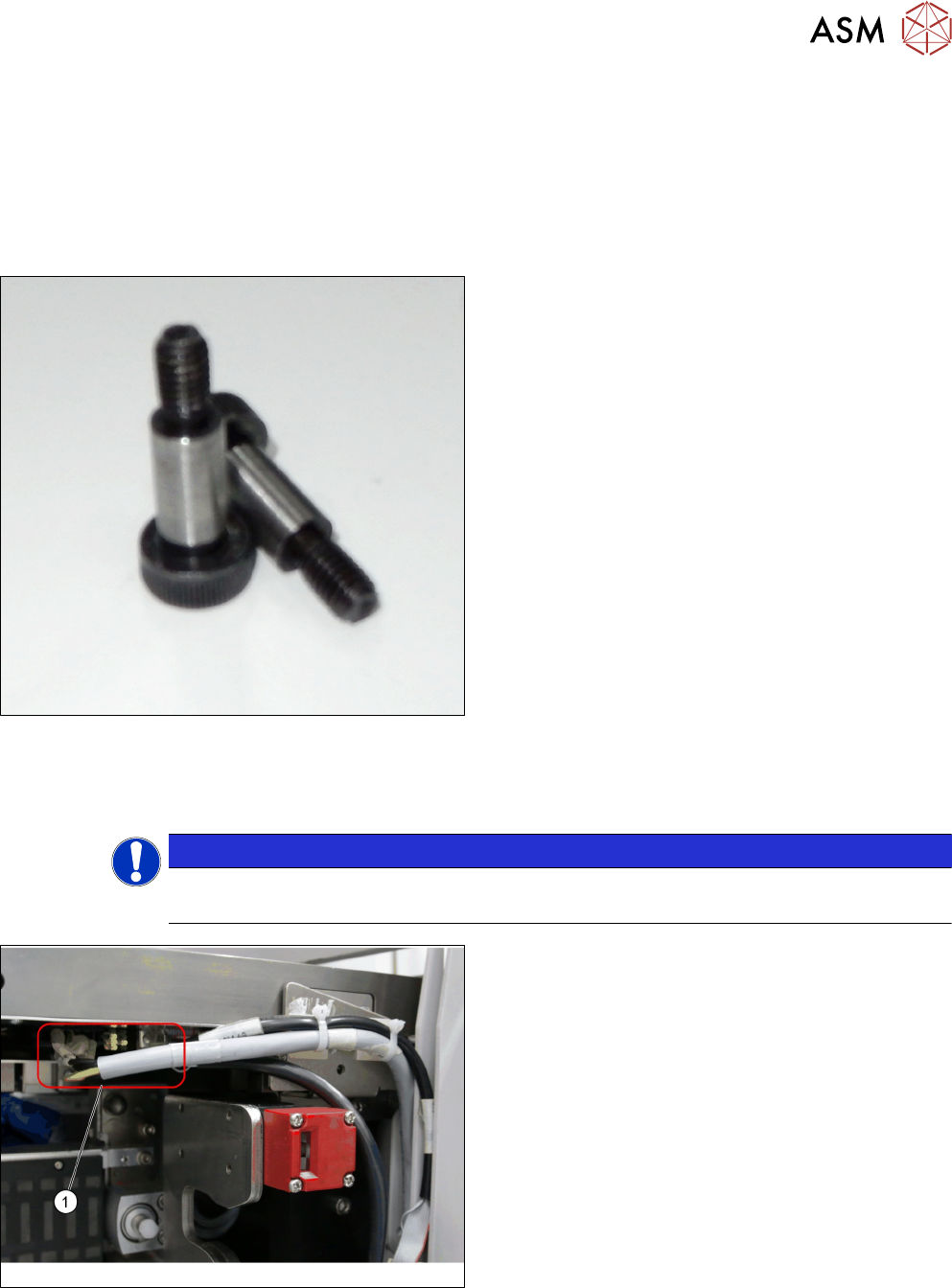
Fitting screw ISO 7379 - 10 x 25-12.9 [03005652-
xx]
Removal
► Switch off the machine, disconnect it from the power supply and secure it to prevent
unauthorized reactivation. Observe the instructions in section 1.2 "Preparatory Work..." [}11].
NOTICE
Cassettes
Make sure all cassettes are removed from the tower before powering down.
► Unplug the cables from the connectors X2.COTI1
and X4.COTI1 in the conveyor base of the
SIPLACE JTF-ML2 (1).
4 Conveyor Mechanics
4.1 Replacing the Fitting Screw [03005652-xx]
70 Service Manual SIPLACE JTF-ML2 08/2017
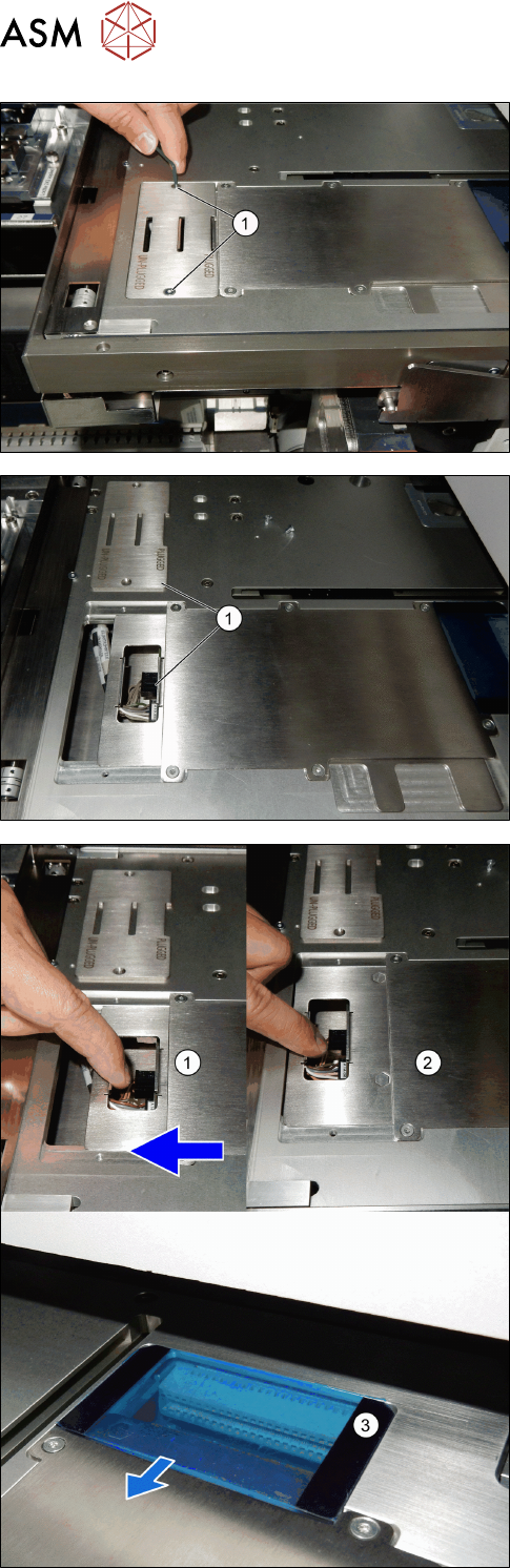
► Remove the two screws ISO 10642 - M3x6-
A2-70 [03082814-xx] (1).
► Remove the PCBA position Cover [03148885-xx]
(1).
► Pull the PCB mounting part [03138496-xx] (1) to-
wards the machine.
ð The PCB mounting part [03138496-xx]
changes from plugged to unplugged position
(2).
ð The power is disconnected (3).
4 Conveyor Mechanics
4.1 Replacing the Fitting Screw [03005652-xx]
Service Manual SIPLACE JTF-ML2 08/2017 71
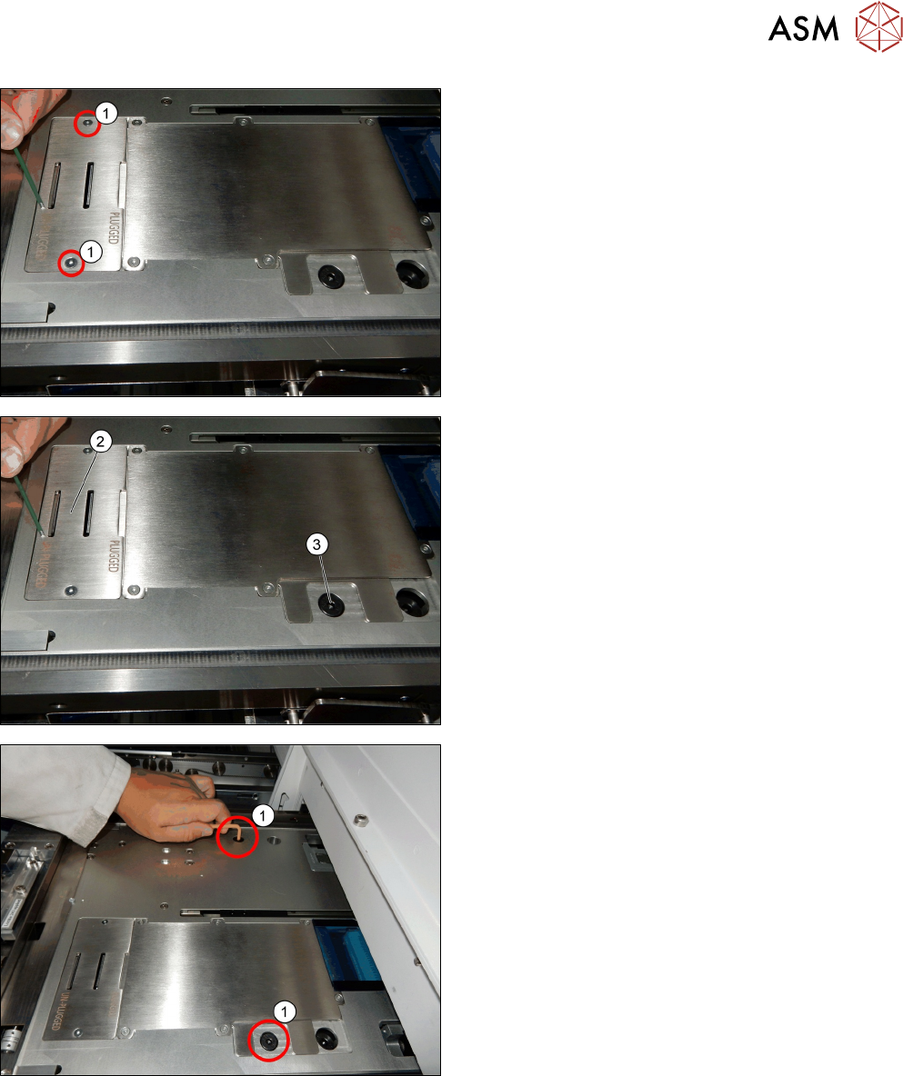
► Reinsert the PCBA position Cover [03148885-xx].
► Fix the two screws ISO 10642 - M3x6-A2-70
[03082814-xx] (1).
The cover now stays in the unplugged position (2).
One of the two screws ISO 7379 - 10 x 25-12.9
[03005652-xx] (3) is accessible.
► Remove the two screws ISO 7379 - 10 x 25-12.9
[03005652-xx] (1).
Installation
► Follow the removal instructions in reverse order for installation.