00198377-01_SM_JTF-ML2_en.pdf - 第78页
4 Conveyor Mechanics 4.2 Removing the Conveyor Driver Unit and its Parts as Preparatory Steps 78 Service Manual SIPLACE JTF-ML2 08/2017 ► Remove the screw ISO 4762 - M 3 x 6-A2-70 [03042541-xx] (1) while holding the conv…
4 Conveyor Mechanics
4.2 Removing the Conveyor Driver Unit and its Parts as Preparatory Steps
Service Manual SIPLACE JTF-ML2 08/2017 77
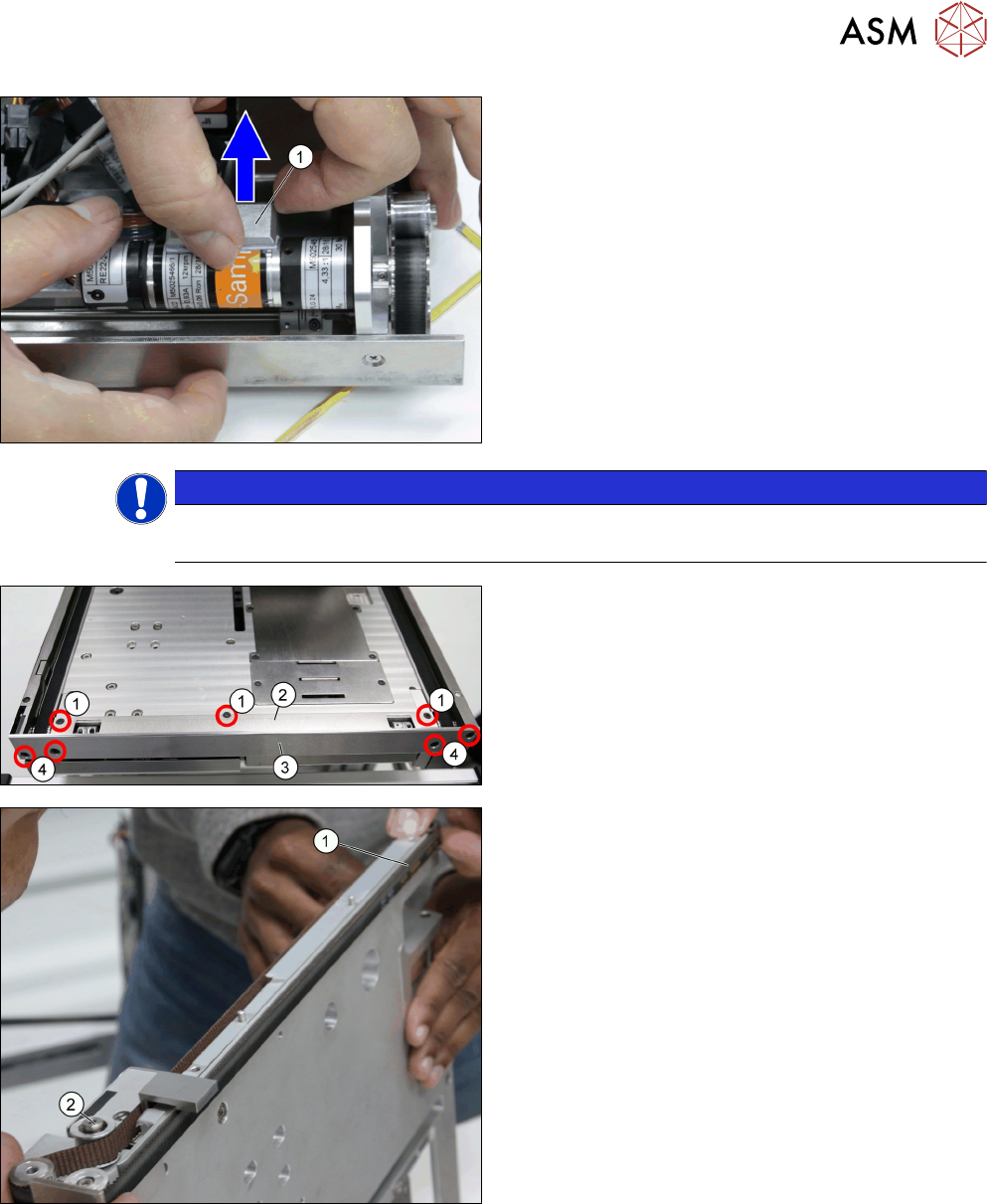
► Remove the Conveyor motor heat transfer block
A [03148017-xx] (1).
NOTICE
Heat transfer interface sheet
Take care not to tear the heat transfer interface sheet.
► Remove the two screws ISO 10642 - M3x6-
A2-70 [03082814-xx] (1).
► Remove the Conveyor top cover [03147570-xx]
(2).
► Remove the two screws ISO 10642 - M3x6-
A2-70 [03082814-xx] (4).
► Remove the Stopper plate [03132873-xx] (3).
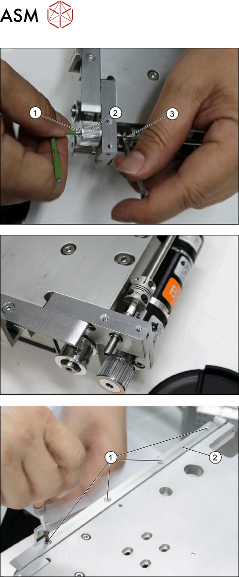
► Loosen the tension pulley (2).
► Carefully remove the Toothed belt 10+-0.1
S2M/726 [03130743-xx] (1).
4 Conveyor Mechanics
4.2 Removing the Conveyor Driver Unit and its Parts as Preparatory Steps
78 Service Manual SIPLACE JTF-ML2 08/2017
► Remove the screw ISO 4762 - M 3 x 6-A2-70
[03042541-xx] (1) while holding the conveyor
shaft (3) with an open ended wrench.
► Remove the Driving pulley S2MZ26 [03128931-
xx] (2).
Driving pulley S2MZ26 [03128931-xx] removed.
► Remove the four screws [ISO 10642 - M3x6-
A2-70 [03082814–xx] (1).
► Remove the Belt support [03133050-xx] (2).
4 Conveyor Mechanics
4.2 Removing the Conveyor Driver Unit and its Parts as Preparatory Steps
Service Manual SIPLACE JTF-ML2 08/2017 79
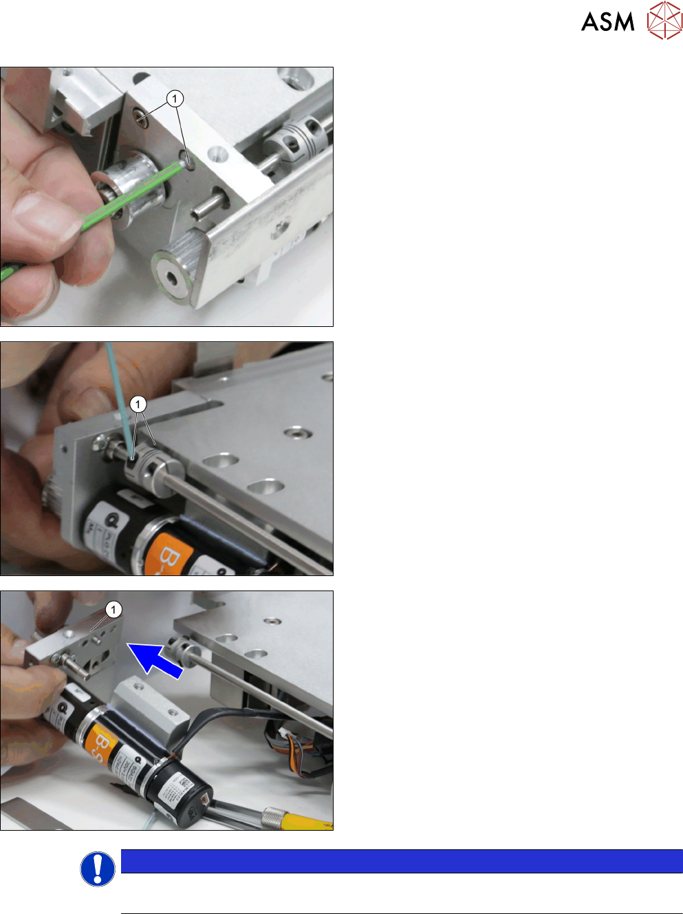
► Remove the two screws ISO 4762 - M 3 x 12-
A2-70 [03042544-xx] (1).
► Loosen the two screws of the Single Disk flexible
Coupling 4x4 [03146598-xx] (1).
► Carefully draw the Conveyor driver unit
[03132255-xx] (1) from the conveyor.
NOTICE
Dowels
Check that two dowels are present before assembling back.