00198377-01_SM_JTF-ML2_en.pdf - 第80页
4 Conveyor Mechanics 4.2 Removing the Conveyor Driver Unit and its Parts as Preparatory Steps 80 Service Manual SIPLACE JTF-ML2 08/2017 ► Remove the screw DIN EN ISO 4026 - M3 x 4- A2-21H [03025540-xx] (1) from the Conve…
4 Conveyor Mechanics
4.2 Removing the Conveyor Driver Unit and its Parts as Preparatory Steps
Service Manual SIPLACE JTF-ML2 08/2017 79
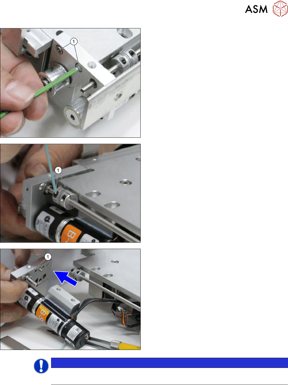
► Remove the two screws ISO 4762 - M 3 x 12-
A2-70 [03042544-xx] (1).
► Loosen the two screws of the Single Disk flexible
Coupling 4x4 [03146598-xx] (1).
► Carefully draw the Conveyor driver unit
[03132255-xx] (1) from the conveyor.
NOTICE
Dowels
Check that two dowels are present before assembling back.
4 Conveyor Mechanics
4.2 Removing the Conveyor Driver Unit and its Parts as Preparatory Steps
80 Service Manual SIPLACE JTF-ML2 08/2017
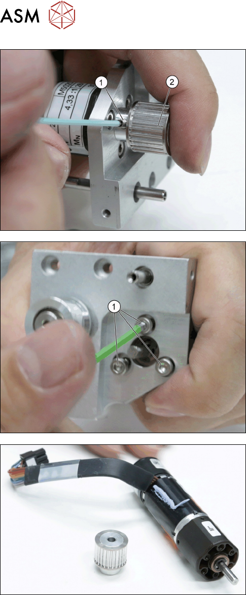
► Remove the screw DIN EN ISO 4026 - M3 x 4-
A2-21H [03025540-xx] (1) from the Conveyor
drive pulley S2MZ26 [03127981-xx] (2).
► Remove the Conveyor drive pulley with set screw
[03156654-xx].
► Remove the three screws ISO 4762 - M 3 x 6-
A2-70 [03042541-xx] (1) from the Motor Assem-
bly, BLDCmotor w/ encoder, Gearbox [03146371-
xx].
► Remove the motor Assembly, BLDCmotor w/ en-
coder,gearbox [03146371-xx].
4 Conveyor Mechanics
4.2 Removing the Conveyor Driver Unit and its Parts as Preparatory Steps
Service Manual SIPLACE JTF-ML2 08/2017 81
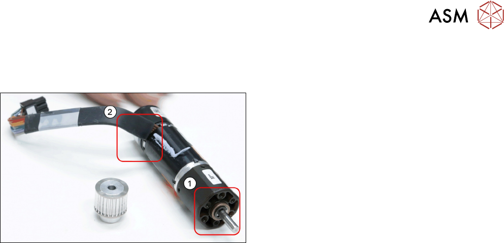
Installation
► Follow the removal instructions in reverse order for installation. Also observe the following in-
structions:
► Please consider the correct angle of the cable (2)
during reassembling as well as the correct screw
holes(1).
► Take care when assembling the set screw to align the flat side of the shaft to the direction
where the set screw is coming in.