00198377-01_SM_JTF-ML2_en.pdf - 第90页
4 Conveyor Mechanics 4.5 Replacing the PCBA Position Cover 90 Service Manual SIPLACE JTF-ML2 08/2017 ► If you want to remove the conveyor from the machine afterwards, pull the PCB mounting part [03138496-xx] (1) towards …
4 Conveyor Mechanics
4.5 Replacing the PCBA Position Cover
Service Manual SIPLACE JTF-ML2 08/2017 89
4.5 Replacing the PCBA Position Cover
Parts, Equipment and Tools
●
Standard tools
●
PCBA position cover [03148885-xx]
Removal
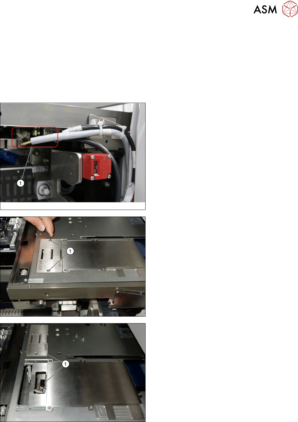
► Switch off the machine, disconnect it from the power supply and secure it to prevent
unauthorized reactivation. Observe the instructions in section 1.2 "Preparatory Work..." [}11].
► Unplug the cables from the connectors X2.COTI1
and X4.COTI1 in the conveyor base of the
SIPLACE JTF-ML2 (1).
► Remove the two screws ISO 10642 - M3x6-
A2-70 [03082814-xx] (1).
► Remove the PCBA position Cover [03148885-xx]
(1).
4 Conveyor Mechanics
4.5 Replacing the PCBA Position Cover
90 Service Manual SIPLACE JTF-ML2 08/2017
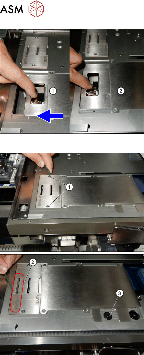
► If you want to remove the conveyor from the
machine afterwards, pull the PCB mounting part
[03138496-xx] (1) towards you.
ð The PCB mounting part [03138496-xx]
changes from PLUGGED to UNPLUGGED
position (2).
► Ensure the PCB is disconnected (3).
Or
► Leave the position as PLUGGED if you have no
further work to do.
Installation
► Reinsert the PCBA position Cover [03148885-xx].
► Fix the two screws ISO 10642 - M3x6-A2-70
[03082814-xx] (1).
ð The cover now stays in the UNPLUGGED
position (2).
ð One of the two screws ISO 7379 - 8 x 16-12.9
[03005644-xx] (3) is accessible.
► Or
ð The cover is still in PLUGGED position.
4 Conveyor Mechanics
4.6 Replacing the E Clamper and Parts
Service Manual SIPLACE JTF-ML2 08/2017 91
4.6 Replacing the E Clamper and Parts
Parts, Equipment and Tools
●
Standard tools
●
E clamper complete [03147300-xx]
Removal
► Switch off the machine, disconnect it from the power supply and secure it to prevent
unauthorized reactivation. Observe the instructions in section 1.2 "Preparatory Work..." [}11].
► Remove the conveyor from the machine (see 2.1.1 "Removing Conveyor from Ma-
chine" [}17]).
► Remove the Conveyor driver unit from the conveyor (see 4.2 "Removing the Conveyor Driver
Unit and its Parts as Preparatory Steps" [}72]).
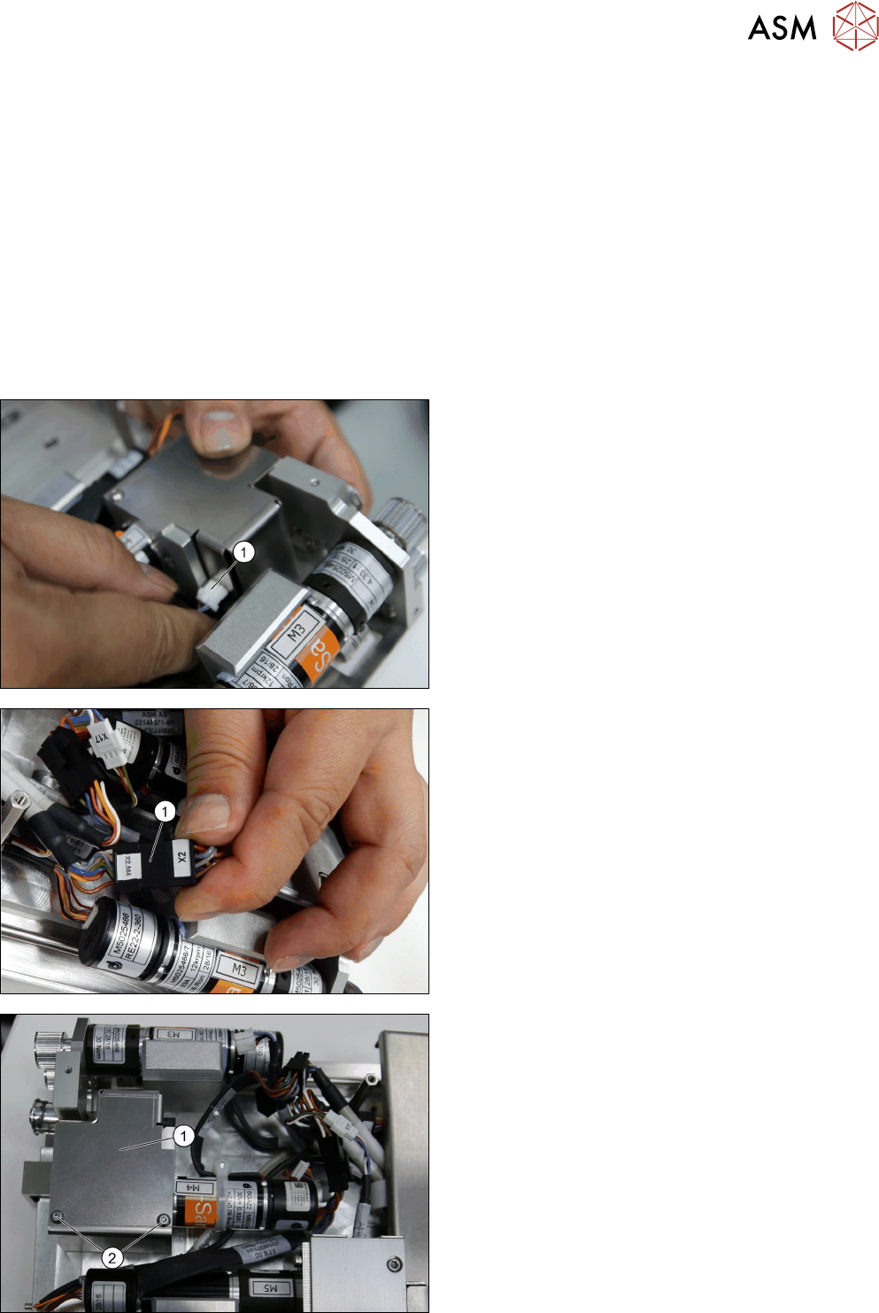
► Make sure to remove the connector for the home
sensor (1).
► Make sure to remove the connector for the motor
(1).
► Remove the two screws DIN EN ISO 7380-M3 x
5-A2-70 [03045193-xx] (2).
► Remove the Clamper cover [03145970-xx] (1).