00198377-01_SM_JTF-ML2_en.pdf - 第94页
4 Conveyor Mechanics 4.6 Replacing the E Clamper and Parts 94 Service Manual SIPLACE JTF-ML2 08/2017 4.6.1 Replacing the Plastic Guide Parts, Equipment and Tools ● Standard tools ● Plastic guide [03145969-xx] Removal ► S…
4 Conveyor Mechanics
4.6 Replacing the E Clamper and Parts
Service Manual SIPLACE JTF-ML2 08/2017 93
Installation
► Follow the removal instructions in reverse order for installation. Also observe the following in-
structions:
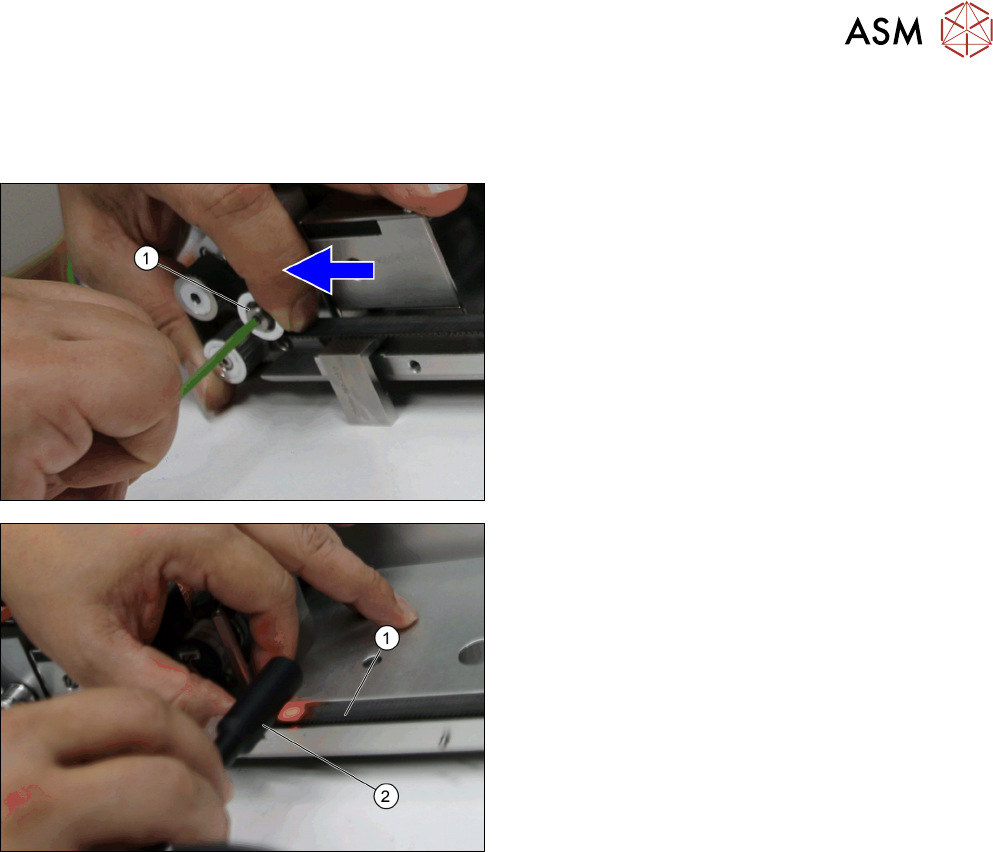
► After you put back the Toothed belt 10+-0.1
S2M/726 [03130743-xx], move and fasten the
Roller f. adjust [03129009-xx] with the loosen
socket head shoulder screw M4x5x16
[03145465-xx] (1) to heighten the tension on the
belt.
► Test the belt tension (1) with a belt tension meas-
uring device (2).
► Repeat the process until the belt tension is at 70
+/-5 Hz.
4 Conveyor Mechanics
4.6 Replacing the E Clamper and Parts
94 Service Manual SIPLACE JTF-ML2 08/2017
4.6.1 Replacing the Plastic Guide
Parts, Equipment and Tools
●
Standard tools
●
Plastic guide [03145969-xx]
Removal
► Switch off the machine, disconnect it from the power supply and secure it to prevent
unauthorized reactivation. Observe the instructions in section 1.2 "Preparatory Work..." [}11].
► Remove the conveyor from the machine (see 2.1.1 "Removing Conveyor from Ma-
chine" [}17]).
► Remove the Conveyor driver unit from the conveyor (see 4.2 "Removing the Conveyor Driver
Unit and its Parts as Preparatory Steps" [}72]).
► Remove the E clamper cpl. [03147300-xx] (See 4.6 "Replacing the E Clamper and
Parts" [}91]).
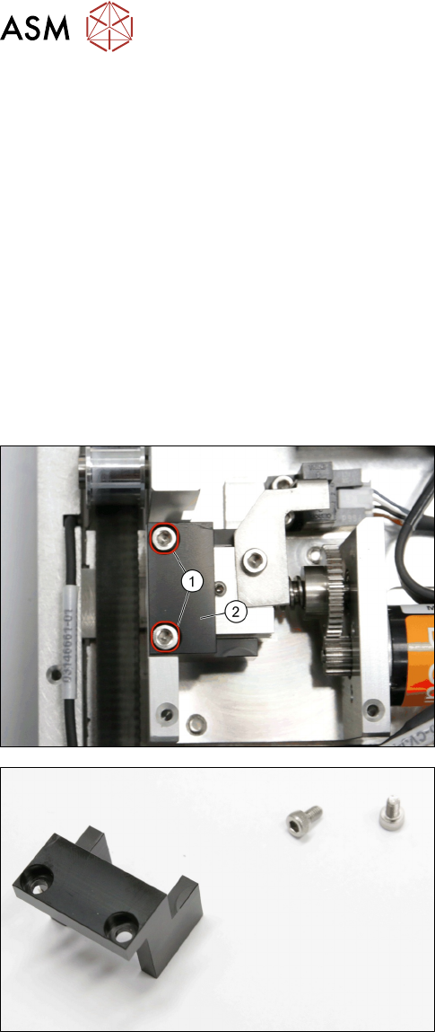
► Remove the two screws ISO 4762 - M 3 x 6-
A2-70 [03042541-xx] (1).
► Remove the Plastic guide [03145969-xx] (2).
Plastic guide [03145969-xx]
Installation
► Follow the removal instructions in reverse order for installation.
4 Conveyor Mechanics
4.7 Replacing the Pusher Unit and Parts
Service Manual SIPLACE JTF-ML2 08/2017 95
4.7 Replacing the Pusher Unit and Parts
Parts, Equipment and Tools
●
Standard tools
●
Pusher unit complete [03147372-xx]
Removal
► Switch off the machine, disconnect it from the power supply and secure it to prevent
unauthorized reactivation. Observe the instructions in section 1.2 "Preparatory Work..." [}11].
► Remove the conveyor (See Removing SIPLACE JTF-ML2 Conveyor from Machine).
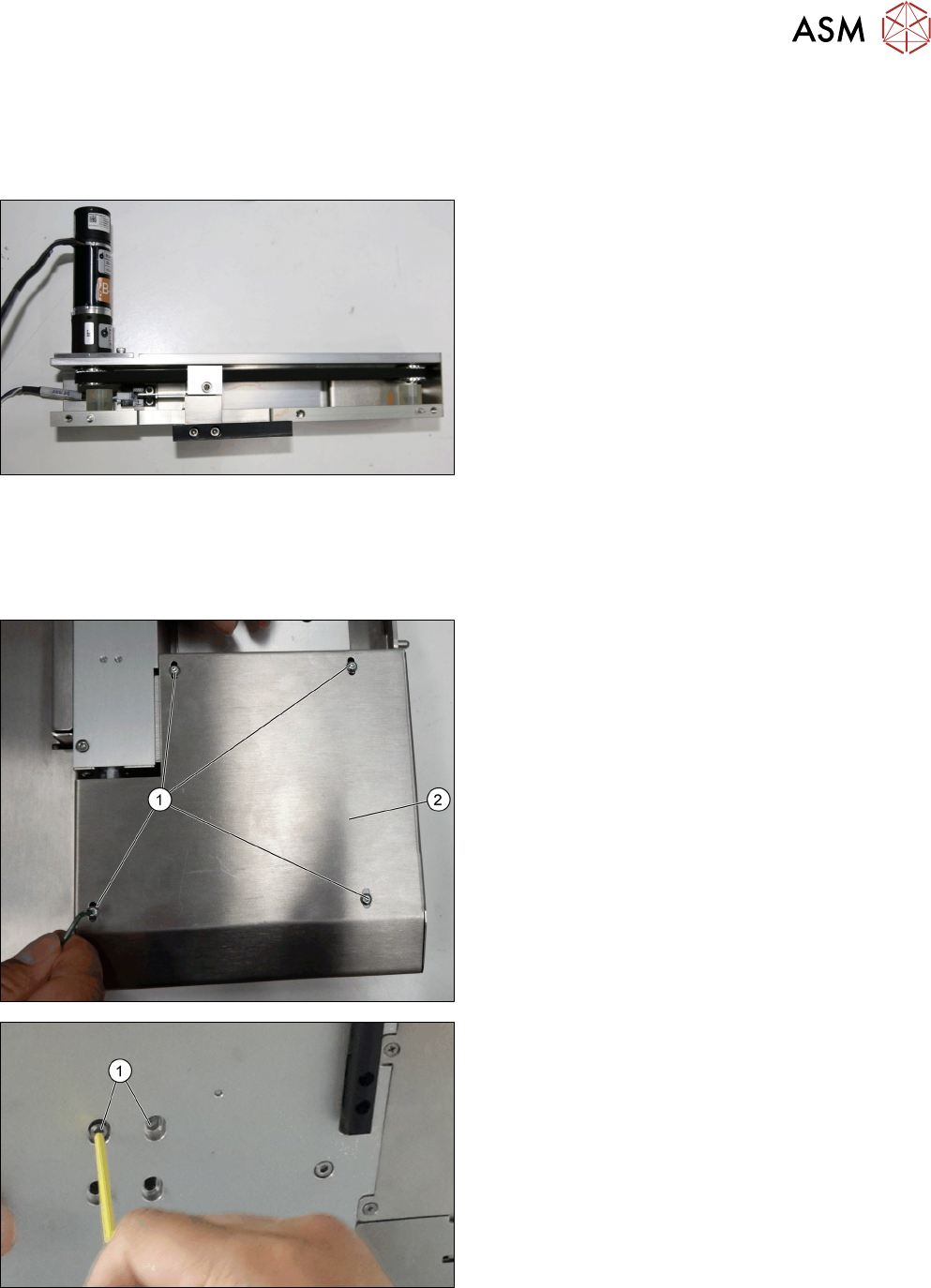
► Remove the four screws DIN EN ISO 7380-M3 x
5-A2-70 [03045193-xx] (1).
► Remove the Conveyor motor cover [03145679-
xx] (2).
► Remove the two screws ISO 4762 - M 4 x 8-
A2-70 [03042551-xx] (1).