00198377-01_SM_JTF-ML2_en.pdf - 第95页
4 Conveyor Mechanics 4.7 Replacing the Pusher Unit and Parts Service Manual SIPLACE JTF-ML2 08/2017 95 4.7 Replacing the Pusher Unit and Parts Parts, Equipment and Tools ● Standard tools ● Pusher unit complete [03147372-…
4 Conveyor Mechanics
4.6 Replacing the E Clamper and Parts
94 Service Manual SIPLACE JTF-ML2 08/2017
4.6.1 Replacing the Plastic Guide
Parts, Equipment and Tools
●
Standard tools
●
Plastic guide [03145969-xx]
Removal
► Switch off the machine, disconnect it from the power supply and secure it to prevent
unauthorized reactivation. Observe the instructions in section 1.2 "Preparatory Work..." [}11].
► Remove the conveyor from the machine (see 2.1.1 "Removing Conveyor from Ma-
chine" [}17]).
► Remove the Conveyor driver unit from the conveyor (see 4.2 "Removing the Conveyor Driver
Unit and its Parts as Preparatory Steps" [}72]).
► Remove the E clamper cpl. [03147300-xx] (See 4.6 "Replacing the E Clamper and
Parts" [}91]).
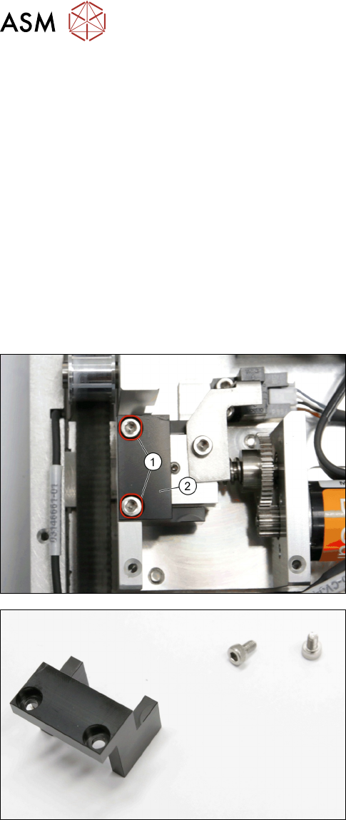
► Remove the two screws ISO 4762 - M 3 x 6-
A2-70 [03042541-xx] (1).
► Remove the Plastic guide [03145969-xx] (2).
Plastic guide [03145969-xx]
Installation
► Follow the removal instructions in reverse order for installation.
4 Conveyor Mechanics
4.7 Replacing the Pusher Unit and Parts
Service Manual SIPLACE JTF-ML2 08/2017 95
4.7 Replacing the Pusher Unit and Parts
Parts, Equipment and Tools
●
Standard tools
●
Pusher unit complete [03147372-xx]
Removal
► Switch off the machine, disconnect it from the power supply and secure it to prevent
unauthorized reactivation. Observe the instructions in section 1.2 "Preparatory Work..." [}11].
► Remove the conveyor (See Removing SIPLACE JTF-ML2 Conveyor from Machine).
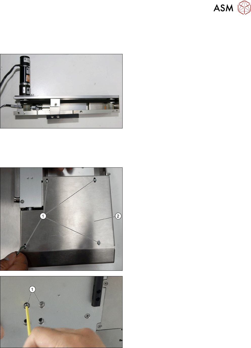
► Remove the four screws DIN EN ISO 7380-M3 x
5-A2-70 [03045193-xx] (1).
► Remove the Conveyor motor cover [03145679-
xx] (2).
► Remove the two screws ISO 4762 - M 4 x 8-
A2-70 [03042551-xx] (1).
4 Conveyor Mechanics
4.7 Replacing the Pusher Unit and Parts
96 Service Manual SIPLACE JTF-ML2 08/2017
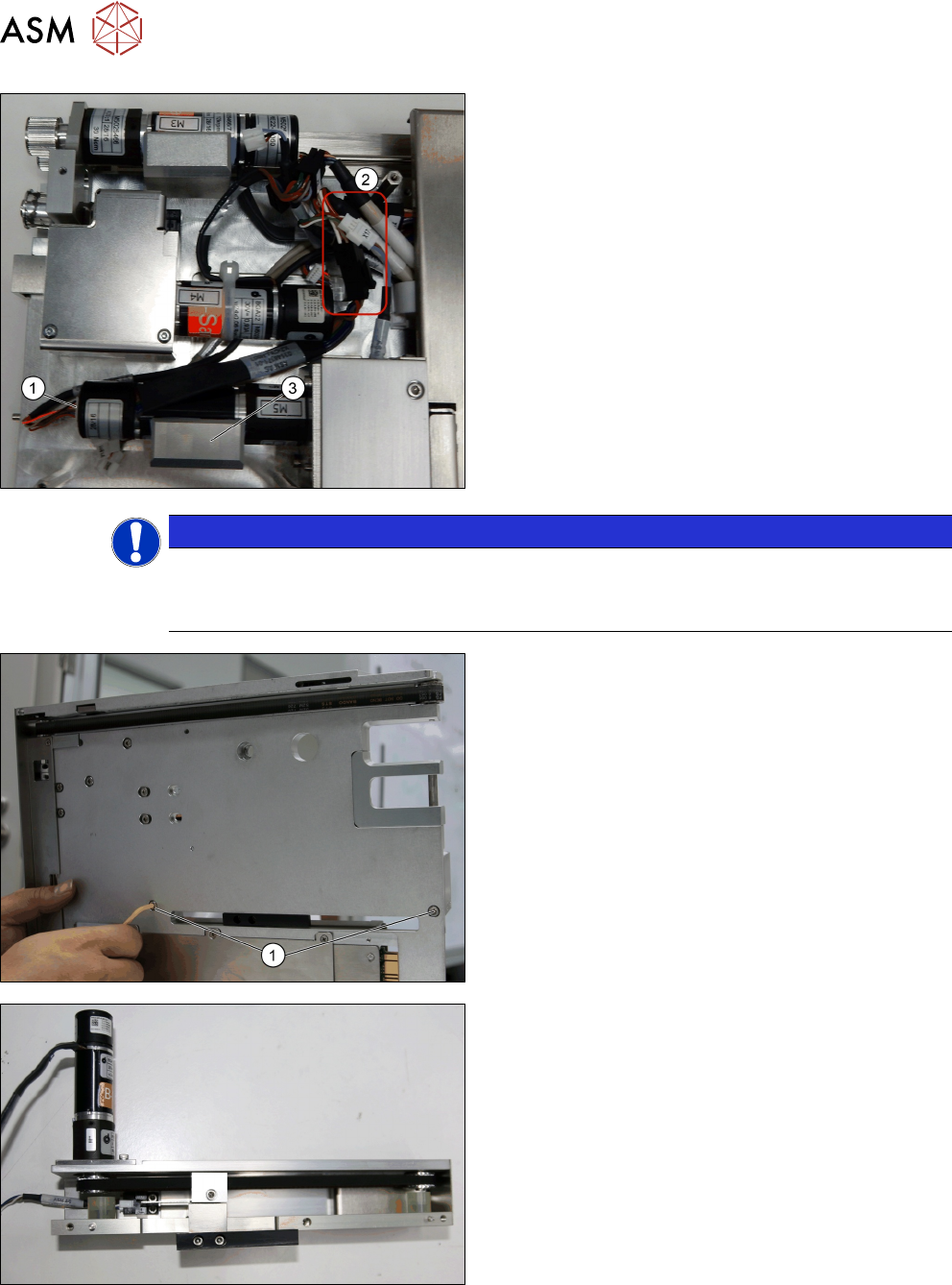
► Remove the Pusher motor heat transfer block A
[03148008-xx] (3)
► Disconnect the connector (1).
► Disconnect the connectors (2).
NOTICE
Heat transfer interface sheet
Take note of the heat transfer interface, do not tear the material (heat transfer interface)
Make sure to push tight against the motor during installation.
► Remove the two screws ISO 4762 - M 4 x 8-
A2-70 [03042551-xx] (1).
► Remove the Pusher unit cpl. [03147372-xx]