00198268-02_GS_SIPLACE-Pro-14.1-R17-1_EN - 第28页
3 T utorial Getting S tarted SIPLACE Pro 14.1 (R17-1) 3.2 Exercise 1: Importing ASCII Centroid Data 05/2017 Edition 28 Create a directory for this exercise My Components\Get ting St arted . Select the following directo…
Getting Started SIPLACE Pro 14.1 (R17-1) 3 Tutorial
05/2017 Edition 3.2 Exercise 1: Importing ASCII Centroid Data
27
Define the following settings in the Step 3 of 6 dialog box:
Click on <Skip> in the header cell and select the designators for the individual columns from
the context menu:
The checkboxes in the Import column will be automatically enabled.
Disable the first line in the Import column if not already disabled - this includes column infor-
mation and not placements (should be automatically disabled).
Click on Next.
In the Step 4 of 6 dialog box, specify that you want to create a new placement list. Select Cre-
ate new from the list box.
Click on Next.
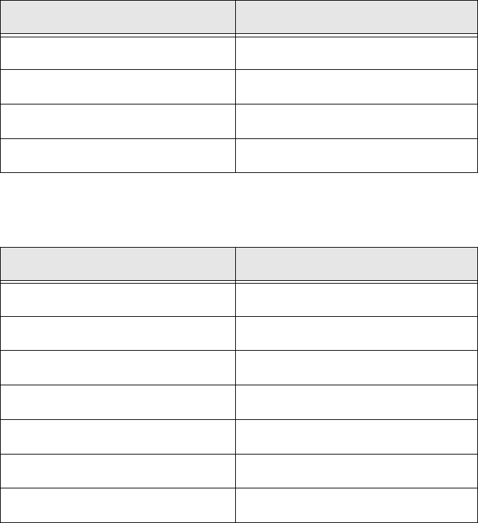
Edit field Option
Import unit mm
Radix Comma
Factor 1.000
Board side designators <None>
Column Column designator
Import <is automatically enabled
Column No. 1 Component
Column No. 2 X
Column No. 3 Y
Column No. 4 Angle
Column No. 5 Reference designator
Column No. 6 <Skip>
3 Tutorial Getting Started SIPLACE Pro 14.1 (R17-1)
3.2 Exercise 1: Importing ASCII Centroid Data 05/2017 Edition
28
Create a directory for this exercise My Components\Getting Started.
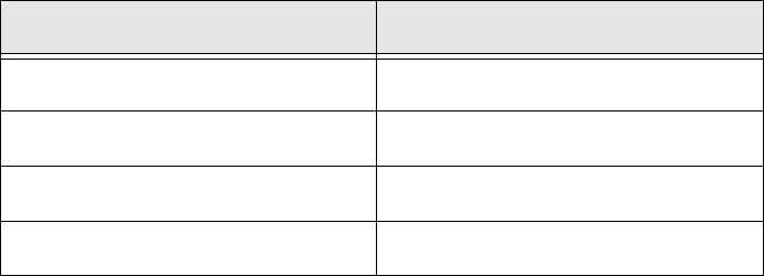
Select the following directories in the Step 5 of 6 dialog box:
3
Click on Next.
The Step 6 of 6 dialog box will appear. The placement list structure will be shown as a preview.
Click on Finish.
the placement list will be generated.
Dialog box/ Option Contents
Components folder (Read from) \Import
Components folder (Write to) \Getting Started (create)
Component Shape folder (Read from) <None>
Component Shape folder (Write to) <None>
Getting Started SIPLACE Pro 14.1 (R17-1) 3 Tutorial
05/2017 Edition 3.2 Exercise 1: Importing ASCII Centroid Data
29
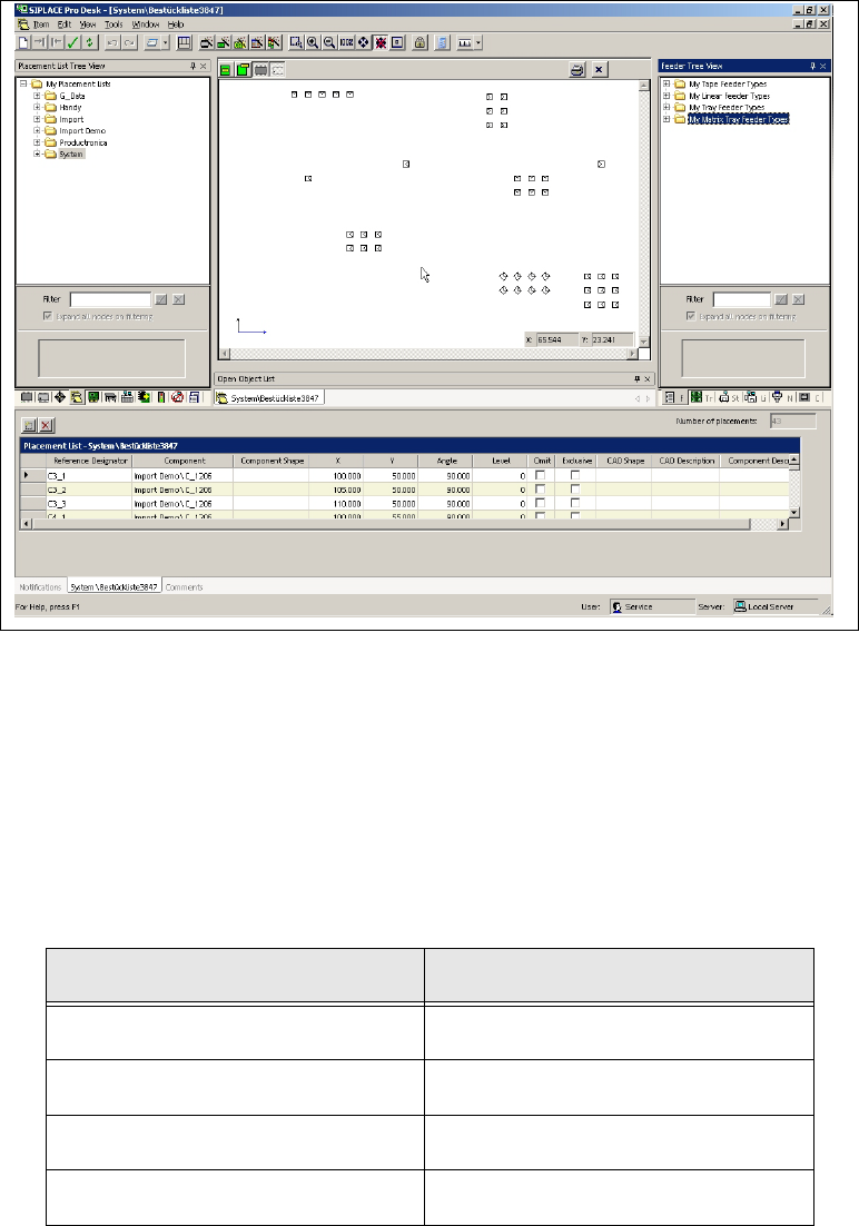
Result 3
A placement list has been created. You now need to assign component shapes (see also section
3.2.2 on page 29). One of the components does not yet have a component shape assigned. This
needs to be created in Exercise 2: Creating a Component Shape. 3
3
Fig. 3 - 2 Result: "Placement list created" screen
3.2.2 Assigning Component Shapes to Components
Select the Component shapes tree view and open the
System directory.
Use the drag & drop function to assign the required component shapes to the placement list.
– Use the data in the following table to help you:
Component Component shape
MMELF 201
0805 103
SOT23 400
1206 105