00198268-02_GS_SIPLACE-Pro-14.1-R17-1_EN - 第32页
3 T utorial Getting S tarted SIPLACE Pro 14.1 (R17-1) 3.3 Exercise 2: Creating a Component Shape 05/2017 Edition 32 Enter the following data in th e Configure Component Shape - S tep 4 of 4 dialog box: Click on Finis…
Getting Started SIPLACE Pro 14.1 (R17-1) 3 Tutorial
05/2017 Edition 3.3 Exercise 2: Creating a Component Shape
31
3.3 Exercise 2: Creating a Component Shape
Aim of exercise 3
A component shape will be created for the component SO20L and then assigned to this compo-
nent. 3
How to create a component shape 3
Open the Wizard with Tools => Component Shape Wizard... or by clicking on the icon.
In the Configure Component Shape - Step 1 of 4 dialog box, select the Integrated Circuits
tab.
Then select 2-Row Component Shape from the Select a Component Shape Type - Step 1 of
4 dialog box.
Click on Next.
In the Configure Component Shape – Step 2 von 4 dialog box, choose the lead type Gull
Wing.
Click on Next.
Select the option Overall width from the Configure Component Shape – Step 3 of 4 dialog box.
– Enter the following data for your component shape:
Click on Next.
Units mm
Body width 7.400
Length (X) 12.800
Pitch 1.270
Lead width 0.430
Lead length 1.400
Contact length 0.400
Height (Z) 2.500
Width (Y) 10.200 (will be preset)
3 Tutorial Getting Started SIPLACE Pro 14.1 (R17-1)
3.3 Exercise 2: Creating a Component Shape 05/2017 Edition
32
Enter the following data in the Configure Component Shape - Step 4 of 4 dialog box:
Click on Finish.
Result 3
The component shape will be shown in the Component Shape Editor and can be edited there. 3
3
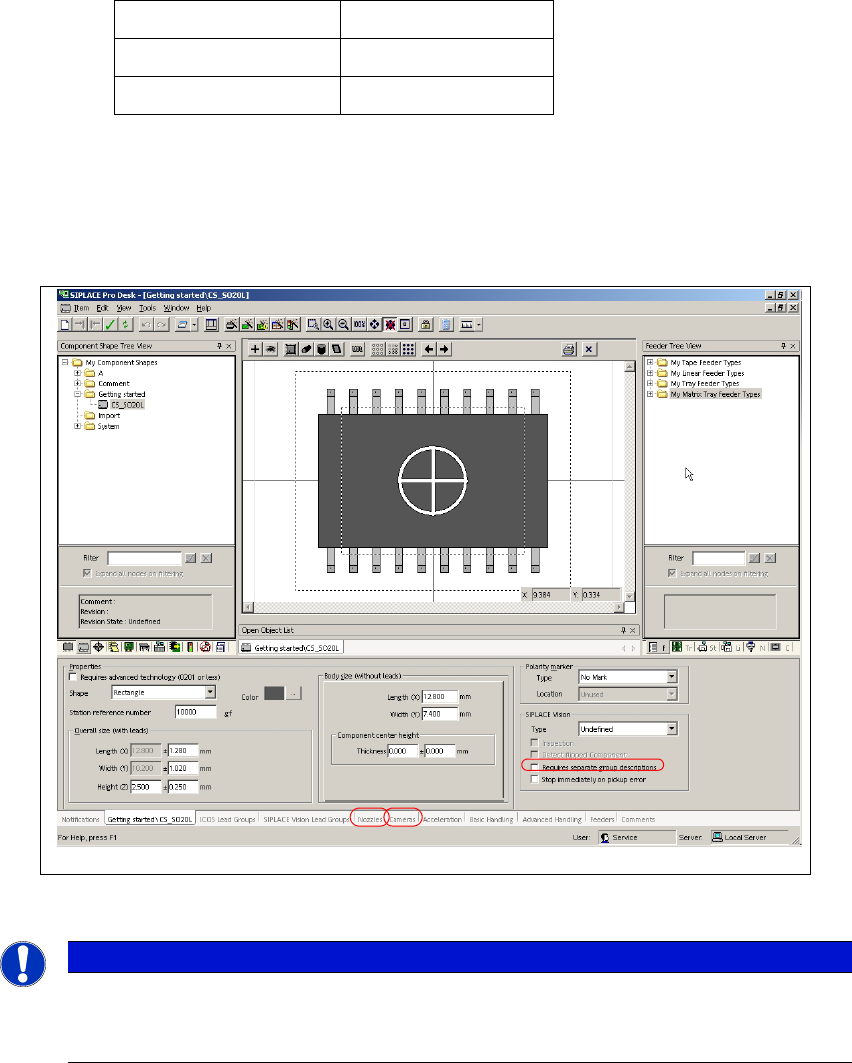
Fig. 3 - 4 Result: "Component Shape created" screen
3
Switch to the Nozzles tab (see Pos.1).
Assign nozzle 817, 917 and 920 with the Add button.
Switch to the Cameras tab (see Pos. 2).
Assign camera RV Camera X (28) 24.2x24.2 and RV Camera X (29) 32x32 with the Add
button.
Total number of leads 20
Top: 10
Bottom: 10
Note
These examples have been kept relatively simple to help new users familiarize them-
selves with the SIPLACE Pro user interface and functions.
Getting Started SIPLACE Pro 14.1 (R17-1) 3 Tutorial
05/2017 Edition 3.3 Exercise 2: Creating a Component Shape
33
Close this component shape.
Create the directory My Component Shapes\Getting Started in the Save As dialog box.
Save this component shape as CS_SO20L.
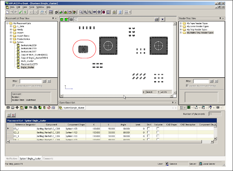
Open the placement list Getting Started\Single_Cluster and use the drag & drop function to
assign the component shape CS_SO20L to the component SO20L.
3
Fig. 3 - 5 Result: "Component Shape created" screen
The placement list has now been completed.
Close the placement list.
Result 3
The new component shape CS_SO20L has been assigned to the component SO20L. Continue
with Exercise 3: Creating a Board for the Placement List. 3
3