IPC 7711A.pdf - 第130页
NOTES IPC-771 1A Number: 3.8.5 Revision: Date: 2/98 Subject: J-Lead Removal P a g e2o f2 Copyright Association Connecting Electronics Industries Provided by IHS under license with IPC Not for Resale No reproduction or ne…
EQUIPMENT REQUIRED
Hot gas (air) reflow system
Correctly sized nozzle
MATERIALS
Cleaner
Flux
PROCEDURE
1. Remove conformal coating (if any) and clean work area of any contamination,
oxides or residues.
2. Install nozzle into the hot gas reflow system and raise nozzle to highest position.
Place PWB assembly onto the work platform.
3. Set system controls to required settings to optimize performance.
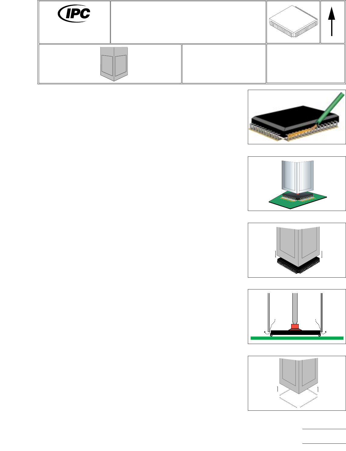
4. Apply flux to component leads. (See Figure 1.)
5. Position component to be removed under nozzle. (See Figure 2.)
6. Lower nozzle and check alignment and make adjustments as needed. (See Fig-
ure 3.)
7. Position nozzle to expose vacuum cup. Turn on vacuum and lower vacuum cup
until it touches component.
8. Lower nozzle to component and commence reflow cycle and observe solder melt
of all leads. (See Figure 4.)
9. Upon completion of reflow cycle, raise nozzle and allow component to cool prior
to board removal from work platform. (See Figure 5.)
Figure 1 Flux Component
Figure 2 Position Component
Figure 3 Lower Nozzle
Figure 4 Melt All Joints
Figure 5 Lift Component
7711A
Rework of
Electronic Assemblies
Revision:
Date: 2/98
J-Lead Removal
Hot Gas Reflow System
Number: 3.8.5
Product Class: R, F, W, C
Skill Level: Advanced
Level of Conformance: High
Material in this manual, IPC-7711 Rework of Electronic Assemblies, was voluntarily established by Technical Committees of
IPC. This material is advisory only and its use or adaptation is entirely voluntary. IPC disclaims all liability of any kind as to the
use, application, or adaptation of this material. Users are also wholly responsible for protecting themselves against all claims
or liabilities for patent infringement. Equipment referenced is for the convenience of the user and does not imply endorsement
by IPC.
Page1of2
Copyright Association Connecting Electronics Industries
Provided by IHS under license with IPC
Not for Resale
No reproduction or networking permitted without license from IHS
--``,``,-`-`,,`,,`,`,,`---

NOTES
IPC-7711A
Number: 3.8.5
Revision:
Date: 2/98
Subject: J-Lead Removal
Page2of2
Copyright Association Connecting Electronics Industries
Provided by IHS under license with IPC
Not for Resale
No reproduction or networking permitted without license from IHS
--``,``,-`-`,,`,,`,`,,`---
EQUIPMENT REQUIRED
Hot air or hot gas re-flow system (representative examples shown by Figures 1-4)
Gas focusing nozzle (sized to BGA dimensions)
Gas supply (if other than ambient atmosphere)
Preheat method (oven, hotplate, high intensity lamp)
OPTIONAL EQUIPMENT
Bake-out (vacuum, convection) oven
Inert gas supply, if used
MATERIALS
Flux-cored solder
Flux
Cleaner
PROCEDURE SUMMARY
The procedure outlined below is generic in nature and identifies the procedural steps
which need be accomplished to effect BGA or CSP removal. Each step must be tai-
lored to accommodate the attributes and characteristics of the specific system being
used (system manufacturers will customarily provide generalized operating proce-
dures which must be further refined to achieve optimum results).
PROCEDURAL PRECONDITIONS
The following preconditions shall be accomplished prior to performing the procedure:
1) Develop a time/temperature profile (TTP) for the specific BGA and PWA. (See
1.9, Process Goals and Guidelines.)
NOTE: If plastic body components are used, see IPC J-STD-020 (Moisture/Reflow
Sensitivity Classification for Plastic Integrated Circuit Surface Mount Devices) for
information on moisture sensitivity classification tests, preconditioning, and attach-
ment.
2) Bake the PWA to remove entrained moisture which may, if not removed, pre-
cipitate measling or delamination.
PROCEDURE STEPS
NOTE: Some systems do not include integrated preheating capability and it may
be necessary to preheat the PWA and BGA separately.
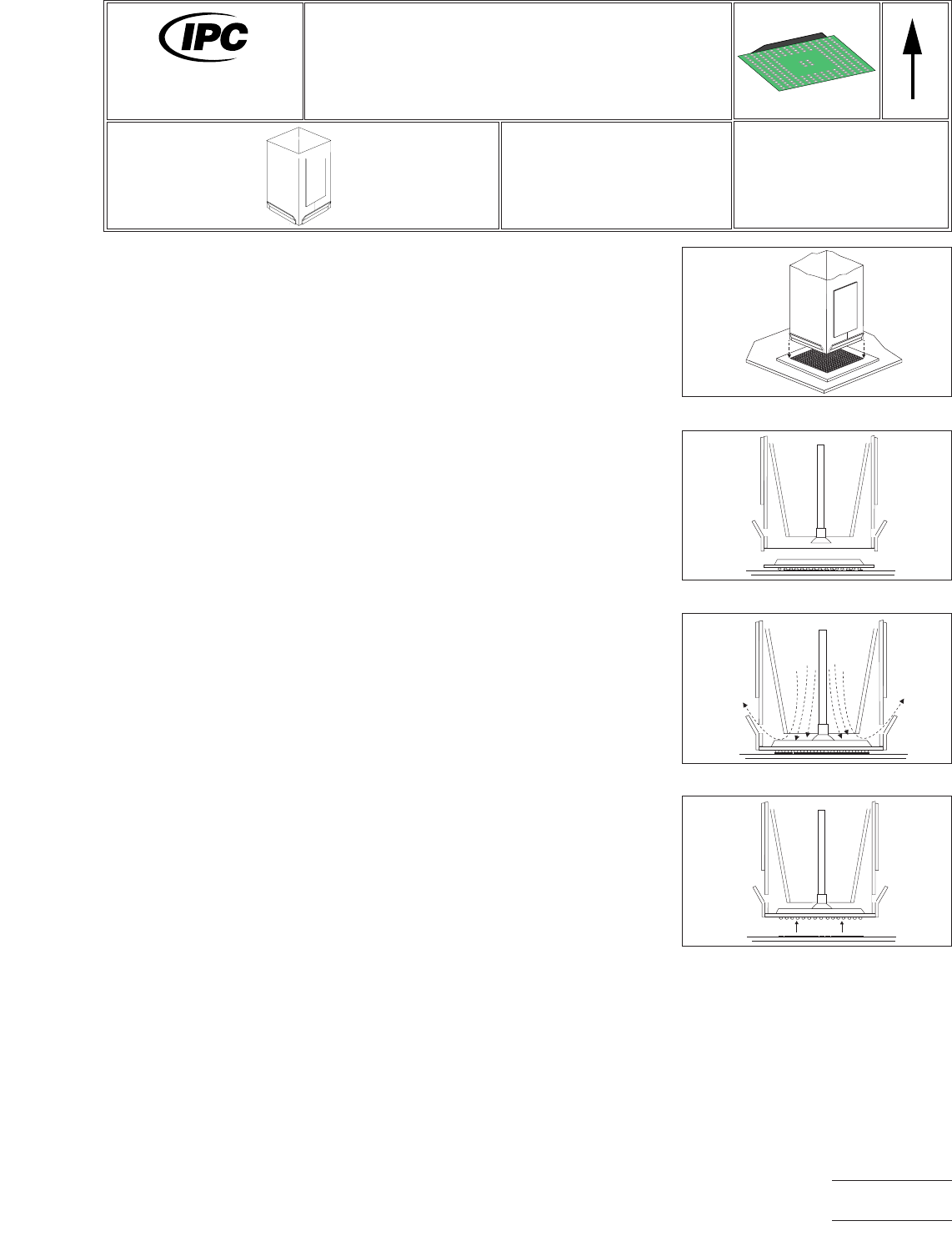
1. Place the PWA in the system work piece holder.
2. Inject flux under the BGA.
3. Set hot gas re-flow system to achieve the TTP defined by procedural analysis.
Figure 1 Align Nozzle
Figure 2 Lower Nozzle
Figure 3 Nozzle to BGA
Figure 4 Raise Nozzle and BGA
7711A
Rework of
Electronic Assemblies
Revision:
Date: 2/98
BGA/CSP Removal
Number: 3.9.1
Product Class: R, F, W, C
Skill Level: Advanced
Level of Conformance: High
Material in this manual, IPC-7711 Rework of Electronic Assemblies, was voluntarily established by Technical Committees of
IPC. This material is advisory only and its use or adaptation is entirely voluntary. IPC disclaims all liability of any kind as to the
use, application, or adaptation of this material. Users are also wholly responsible for protecting themselves against all claims
or liabilities for patent infringement. Equipment referenced is for the convenience of the user and does not imply endorsement
by IPC.
Page1of2
Copyright Association Connecting Electronics Industries
Provided by IHS under license with IPC
Not for Resale
No reproduction or networking permitted without license from IHS
--``,``,-`-`,,`,,`,`,,`---