IPC 7711A.pdf - 第156页
9. At the end of the timer cycle, wait at least 5 seconds for the solder to solidify, then remove the board. 10. Clean the flux residue, if required, and inspect. NOTES IPC-771 1A Number: 5.2.1 Revision: Date: 2/98 Subje…
EQUIPMENT REQUIRED
Solder fountain
Chimney or nozzle to match part
Removal tool
Pallet to hold board over fountain
Preheat oven
MATERIALS
Flux
Cleaner
Heat resistant, antistatic gloves
Protective face gear
Heat resistant tape
PROCEDURE
This procedure variation is for components or connectors with sturdy leads that do
not readily bend.
This process is for experienced operators only. Caution must be exercised due to
working with hot, molten solder.
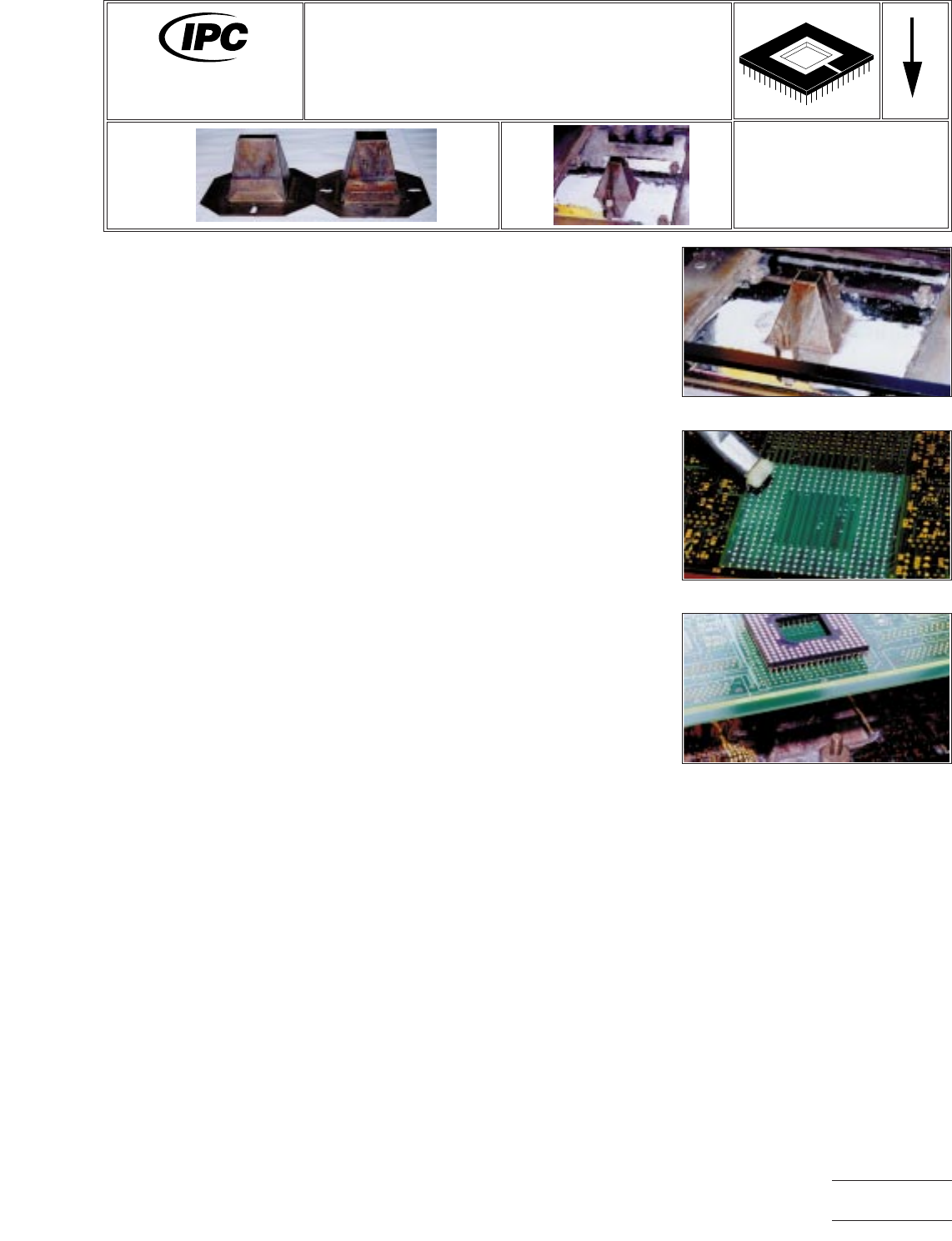
1. Attach the correct nozzle or chimney to the solder pot. This operation must be
done with proper care per solder fountain supplier’s instructions. (See Figure 1.)
2. Set solder fountain pot control to the required temperature for soldering that
particular component into that particular board. Wait until solder pot reaches the
set temperature.
3. Set the timer (if applicable) for the amount of time the fountain is to be running
for that particular part.
4. The area around the rework site may be masked with a high temperature resis-
tant tape, or similar material, to protect the adjacent area during rework. (See
Figure 2.)
5. Preheat the new component and the board to the desired temperature, taking
into consideration component thermal restrictions and glass transition tempera-
ture T
g
of the board material.
6. Flux the board on the top and bottom side at the site of the new component.
The component leads may also be fluxed, depending on the board and compo-
nent leads. Place the component on the board in its correct site. (See Figure 2.)
7. Place the board on the pallet, over the solder fountain with the component sit-
ting in location and trip the solder fountain timer. (See Figure 3.)
8. As the solder in the holes reflows, the component may have to be reoriented to
drop into the holes.
Figure 1 Attach Nozzle
Figure 2 Flux
Figure 3 Place Over Solder Fountain
7711A
Rework of
Electronic Assemblies
Revision:
Date: 2/98
PGA and Connector Installation
Solder Fountain Method with PTH Prefilled
Number: 5.2.1
Product Class: R, F, W, C
Skill Level: Expert
Level of Conformance: Medium
Material in this manual, IPC-7711 Rework of Electronic Assemblies, was voluntarily established by Technical Committees of
IPC. This material is advisory only and its use or adaptation is entirely voluntary. IPC disclaims all liability of any kind as to the
use, application, or adaptation of this material. Users are also wholly responsible for protecting themselves against all claims
or liabilities for patent infringement. Equipment referenced is for the convenience of the user and does not imply endorsement
by IPC.
Page1of2
Copyright Association Connecting Electronics Industries
Provided by IHS under license with IPC
Not for Resale
No reproduction or networking permitted without license from IHS
--``,``,-`-`,,`,,`,`,,`---

9. At the end of the timer cycle, wait at least 5 seconds for the solder to solidify,
then remove the board.
10. Clean the flux residue, if required, and inspect.
NOTES
IPC-7711A
Number: 5.2.1
Revision:
Date: 2/98
Subject: PGA and Connector Installation
Page2of2
Copyright Association Connecting Electronics Industries
Provided by IHS under license with IPC
Not for Resale
No reproduction or networking permitted without license from IHS
--``,``,-`-`,,`,,`,`,,`---
EQUIPMENT REQUIRED
Hot air pencil
Hot air tip
Solder paste dispenser
Tweezers
MATERIALS
Solder paste
Cleaner
Solder paste dispense needles
Tissue/wipe
PROCEDURE
NOTE:
Preheating is recommended for sensitive components. (i.e., chip capaci-
tors.)
1. Install tip into hot air pencil.
2. Start with tip temperature of approximately 315°C and change as necessary.
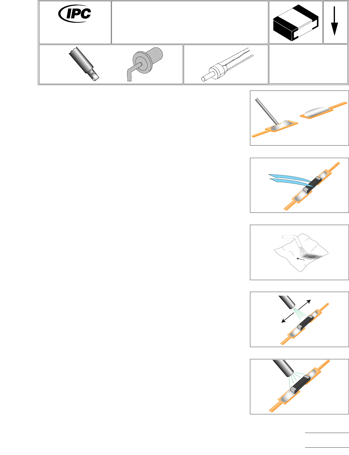
3. Adjust pressure output so hot air scorches a tissue from approximately 0.5 cm
away. (See Figure 3.)
4. Apply a small bead of solder paste to each land using a dispenser. (See Figure
1.)
5. Position component onto lands using tweezers. (See Figure 2.)
6. Direct hot air over component with tip at a distance of 2.5 cm to pre-dry solder
paste. (See Figure 4.)
7. When pre-drying is observed (paste has dull, flat appearance), move tip closer
(0.5 cm) and heat until complete solder melt is observed. (See Figure 5.)
8. Return hot air pencil to its stand.
9. Clean, if required, and inspect.
Figure 1 Apply Solder Paste
Figure 2 Position Component
Figure 3 Adjust Pressure
Figure 4 Pre-dry Paste
Figure 5 Melt Joints
7711A
Rework of
Electronic Assemblies
Revision:
Date: 2/98
Chip Installation
Solder Paste Method/Hot air Pencil
Number: 5.3.1
Product Class: R, F, C, W
Skill Level: Intermediate
Level of Conformance: High
Material in this manual, IPC-7711 Rework of Electronic Assemblies, was voluntarily established by Technical Committees of
IPC. This material is advisory only and its use or adaptation is entirely voluntary. IPC disclaims all liability of any kind as to the
use, application, or adaptation of this material. Users are also wholly responsible for protecting themselves against all claims
or liabilities for patent infringement. Equipment referenced is for the convenience of the user and does not imply endorsement
by IPC.
Page1of2
Copyright Association Connecting Electronics Industries
Provided by IHS under license with IPC
Not for Resale
No reproduction or networking permitted without license from IHS
--``,``,-`-`,,`,,`,`,,`---