IPC 7711A.pdf - 第162页
NOTES IPC-771 1A Number: 5.5.1 Revision: A Date: 5/02 Subject: Gull Wing Installation P a g e2o f2 Copyright Association Connecting Electronics Industries Provided by IHS under license with IPC Not for Resale No reproduc…
EQUIPMENT REQUIRED
Soldering system
Flat faced or cup-shaped tip
Damp sponge
Vacuum pick-up tool
OPTIONAL EQUIPMENT
Tweezers
MATERIALS
Flux-cored solder
Flux
Cleaner
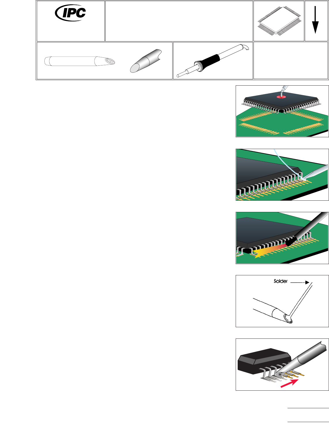
PROCEDURE
1. Install selected tip into the soldering handpiece.
2. Start with tip temperature of approximately 315°C and change as necessary.
3. Position the component ensuring proper lead-to-land alignment. Hold the com-
ponent in place using the vacuum pick-up tool or tweezers. (See Figure 1.)
4. Apply flux and tack solder opposing corner leads. (See Figure 2.)
5. Apply flux to remaining lead/land areas. (See Figure 3.)
6. Clean tip using a damp sponge.
7. Apply solder to tip to create a bead of molten solder. (See Figure 4.)
8. Position tip so the solder bead contacts the top portion of leads. Slowly move
tip over the row of leads to form proper solder fillets at each joint. (See Figure
5.)
9. Repeat steps 7 through 8 on remaining sides of component.
10. Re-tin tip with solder.
11. Clean, if required, and inspect.
Figure 1 Position Component
Figure 2 Tack Lead
Figure 3 Flux Leads
Figure 4 Fill Tip
Figure 5 Solder Component
7711A
Rework of
Electronic Assemblies
Revision: A
Date: 5/02
Gull Wing Installation
Multi-Lead Method – Top of Lead
Number: 5.5.1
Product Class: R, F, W, C
Skill Level: Advanced
Level of Conformance: High
Material in this manual, IPC-7711 Rework of Electronic Assemblies, was voluntarily established by Technical Committees of
IPC. This material is advisory only and its use or adaptation is entirely voluntary. IPC disclaims all liability of any kind as to the
use, application, or adaptation of this material. Users are also wholly responsible for protecting themselves against all claims
or liabilities for patent infringement. Equipment referenced is for the convenience of the user and does not imply endorsement
by IPC.
Page1of2
Copyright Association Connecting Electronics Industries
Provided by IHS under license with IPC
Not for Resale
No reproduction or networking permitted without license from IHS
--``,``,-`-`,,`,,`,`,,`---

NOTES
IPC-7711A
Number: 5.5.1
Revision: A
Date: 5/02
Subject: Gull Wing Installation
Page2of2
Copyright Association Connecting Electronics Industries
Provided by IHS under license with IPC
Not for Resale
No reproduction or networking permitted without license from IHS
--``,``,-`-`,,`,,`,`,,`---
EQUIPMENT REQUIRED
Soldering system
Flat faced or cup-shaped tip
MATERIALS
Flux
Flux-cored solder
NOTE
This technique is most effective with very fine pitch components. Long leads may not
be able to get enough solder to the heel to form a proper fillet without overheating
the land. This procedure is recommended for temperature sensitive components.
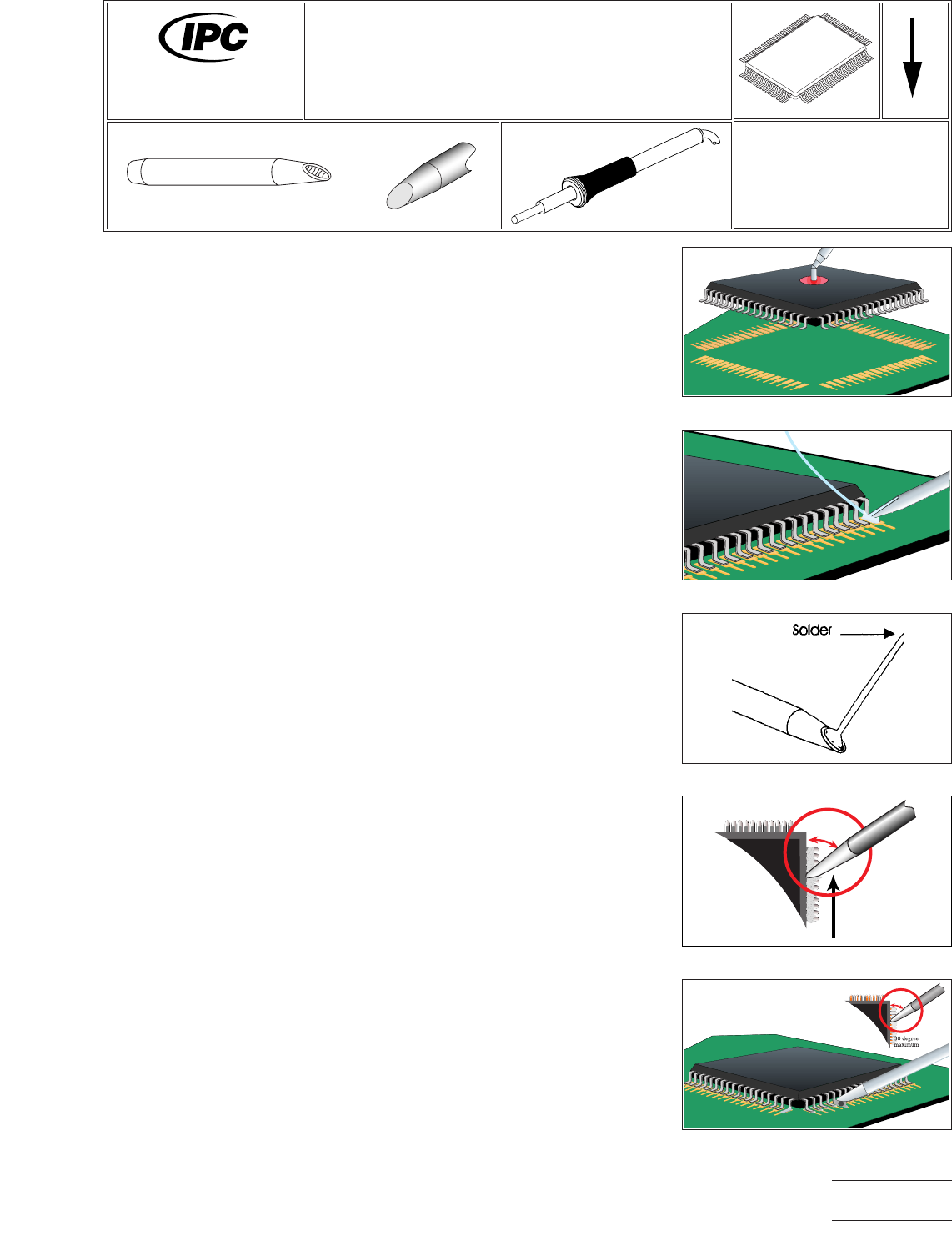
PROCEDURE
1. Install selected tip into the soldering handpiece.
2. Start with tip temperature of approximately 315°C and change as necessary.
3. Align the component carefully to the lands. (See Figure 1.)
4. Flux and tack the leads at opposing corners to fix the component to the board.
(See Figure 2.)
5. Wipe the excess solder from the tip and make sure that the face of the tip is
shiny and wettable.
6. Apply enough solder to cover approximately one-third of the tip. The amount of
solder will vary with the number and pitch of the leads. For fewer leads, or finer
pitch leads, apply less solder. Place the solder at the edge of the tip face that
will meet the leads, rather than directly at the tip. (See Figure 3.)
7. Flux the first row of leads to be soldered. Start the soldering process with a row
that has not been tacked, or from the opposite end of the row from the tack if
the component only has two rows of leads.
8. Bring the tip down at an angle to the point where the toe of the lead meets the
land, so that the edge with solder on it is on the land, but the face is tilted away
from the component. The side of the tip will be in contact with the lead. (See
Figure 4.)
9. Hold the tip so the shaft runs parallel to the row of leads, that is, with the side
of the tip toward the side of the component. The angle between the side of the
tip and the side of the component would ideally be zero for maximized heat
transfer, but can be up to 30° depending on operator preference. (See Figure
5.)
10. Immediately begin running the tip down the toes of the leads. Do not apply
pressure to the leads.
11. Repeat steps 5 through 10 for each row of leads.
Figure 1 Align Component
Figure 2 Flux & Tack 2 Corner Leads
Figure 3 Apply Solder to 1/3 Tip
Figure 4 45° or Less
45 degree
maximum
Figure 5 Draw Tip Side Down Toes
7711A
Rework of
Electronic Assemblies
Revision:
Date: 2/98
Gull Wing Installation
Multi-Lead Method – Toe Tip
Number: 5.5.2
Product Class: R, F, W, C
Skill Level: Advanced
Level of Conformance: High
Material in this manual, IPC-7711 Rework of Electronic Assemblies, was voluntarily established by Technical Committees of
IPC. This material is advisory only and its use or adaptation is entirely voluntary. IPC disclaims all liability of any kind as to the
use, application, or adaptation of this material. Users are also wholly responsible for protecting themselves against all claims
or liabilities for patent infringement. Equipment referenced is for the convenience of the user and does not imply endorsement
by IPC.
Page1of2
Copyright Association Connecting Electronics Industries
Provided by IHS under license with IPC
Not for Resale
No reproduction or networking permitted without license from IHS
--``,``,-`-`,,`,,`,`,,`---