IPC 7711A.pdf - 第180页
NOTES IPC-771 1A Number: 5.6.4 Revision: Date: 2/98 Subject: J-Lead Installation P a g e2o f2 Copyright Association Connecting Electronics Industries Provided by IHS under license with IPC Not for Resale No reproduction …
EQUIPMENT REQUIRED
Soldering system
Flat faced tip or cup
Flux
Flux-cored solder
MATERIALS
Cleaner
Tissue/wipe
PROCEDURE
1. Install tip into soldering handpiece.
2. Start with tip temperature of approximately 315°C and change as necessary.
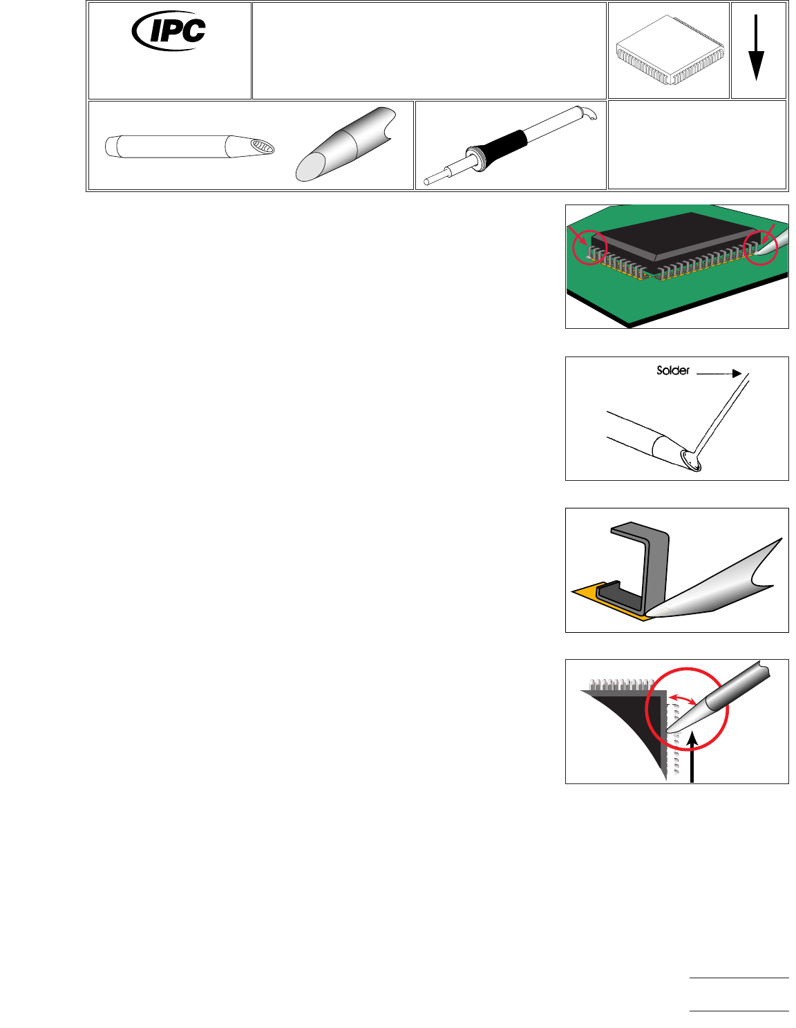
3. Align the component carefully and solder it to the board at diagonally opposite
corners to fix it in place. (See Figure 1.)
4. Clean tip using damp sponge.
5. Apply solder to the face of the tip to cover approximately 1/2 of the face, keep-
ing the solder down toward the end of the tip, and add about the same amount
to the top end of the tip, also at the heel. The precise amount of solder will vary
between different types of components. (See Figure 2.)
6. Work with one side at a time, and start with a side that does not include a tacked
joint.
7. Bring the tip in at a 45° angle in relation to the row of leads. The tip will make
contact with the leads and lands where they meet. (See Figure 3.)
8. Maintaining the same angle, draw the tip down the row of leads slowly and
steadily. (See Figure 4.)
9. Clean, if required, and inspect.
Figure 1 Solder at Corners
Figure 2 Apply Solder to Tip
Figure 3 Tip in Contact with Heel
Figure 4 Draw Tip Down
45 degree
maximum
7711A
Rework of
Electronic Assemblies
Revision:
Date: 2/98
J-Lead Installation
Multi-Lead Method
Number: 5.6.4
Product Class: R, F, W, C
Skill Level: Intermediate
Level of Conformance: High
Material in this manual, IPC-7711 Rework of Electronic Assemblies, was voluntarily established by Technical Committees of
IPC. This material is advisory only and its use or adaptation is entirely voluntary. IPC disclaims all liability of any kind as to the
use, application, or adaptation of this material. Users are also wholly responsible for protecting themselves against all claims
or liabilities for patent infringement. Equipment referenced is for the convenience of the user and does not imply endorsement
by IPC.
Page1of2
Copyright Association Connecting Electronics Industries
Provided by IHS under license with IPC
Not for Resale
No reproduction or networking permitted without license from IHS
--``,``,-`-`,,`,,`,`,,`---

NOTES
IPC-7711A
Number: 5.6.4
Revision:
Date: 2/98
Subject: J-Lead Installation
Page2of2
Copyright Association Connecting Electronics Industries
Provided by IHS under license with IPC
Not for Resale
No reproduction or networking permitted without license from IHS
--``,``,-`-`,,`,,`,`,,`---
EQUIPMENT REQUIRED
Hot air or hot gas reflow system (representative examples shown by Figures 1-4)
Gas focusing nozzle (sized to BGA dimensions)
Gas supply (if other than ambient atmosphere)
Preheat method (oven, hotplate, high intensity lamp)
OPTIONAL EQUIPMENT
Bake-out (vacuum, convection) oven
X-ray inspection system
Forced (ambient) air cooling system
Inert gas supply, if used
Microscope/vision system
MATERIALS
Flux-cored solder
Flux
Cleaner
PROCEDURE SUMMARY
The procedure outlined below is generic in nature and identifies the procedural steps
which need be accomplished to effect BGA or CSP installation. Each step must be
tailored to accommodate the attributes and characteristics of the specific system
being used (system manufacturers will customarily provide generalized operating
procedures which must be further refined to achieve optimum results).
PROCEDURAL PRECONDITIONS
The following preconditions shall be accomplished prior to performing the procedure:
1) Develop a time/temperature profile (TTP) for the specific BGA and PWA. (See
1.9, Process Goals and Guidelines.)
NOTE: If plastic body or tape body components are used, see IPC J-STD-
020 (Moisture/Reflow Sensitivity Classification for Plastic Integrated Circuit
Surface Mount Devices) for information on moisture sensitivity classification
tests, preconditioning, and attachment.
2) Bake the PWA to remove entrained moisture which may, if not removed,
precipitate measling or delamination.
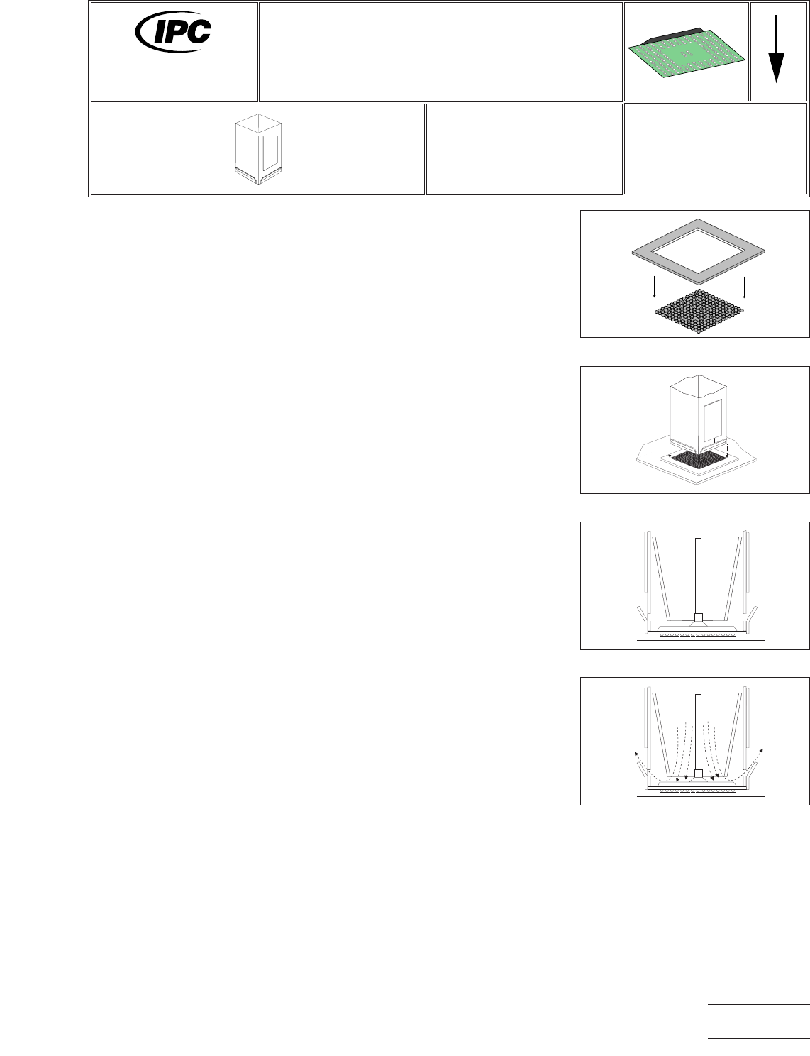
Figure 1 Align Template
Figure 2 Align Nozzle
Figure 3 Ball/Land Contact
Figure 4 Begin Reflow
7711A
Rework of
Electronic Assemblies
Revision:
Date: 2/98
BGA/CSP Installation
Using Wire Solder to Prefill Lands
Number: 5.7.1
Product Class: R,F,W,C
Skill Level: Advanced
Level of Conformance: High
Material in this manual, IPC-7711 Rework of Electronic Assemblies, was voluntarily established by Technical Committees of
IPC. This material is advisory only and its use or adaptation is entirely voluntary. IPC disclaims all liability of any kind as to the
use, application, or adaptation of this material. Users are also wholly responsible for protecting themselves against all claims
or liabilities for patent infringement. Equipment referenced is for the convenience of the user and does not imply endorsement
by IPC.
Page1of2
Copyright Association Connecting Electronics Industries
Provided by IHS under license with IPC
Not for Resale
No reproduction or networking permitted without license from IHS
--``,``,-`-`,,`,,`,`,,`---