IPC 7711A.pdf - 第196页
6. TINNING Backgr ound: Once a conductor is exposed to the envi- ronment, oxidation begins to take place. The tinning of a conductor is important to ensure a quality solder con- nection. T inning stranded wire reduces th…

8.1 Splicing
1. THE PROCESS OF WIRE SPLICING IS USED IN TWO
CASES:
a. When a self-lead component (inductor, transformer,
choke, etc.) is installed (either during assembly or
as a replacement for a failed component) and,
b. In the process of repairing a damaged wire when
removal and replacement of the entire wire length
is not feasible.
2. THE FOUR MOST COMMON SPLICES USED ARE:
• Mesh Splices Mesh splices require the least wire
length in order to complete the splice and result in a
splice diameter only slightly larger than the diameter
of the wire used.
• Wrap Splices Wrap splices require a longer wire
length in order to complete the splice and have a
splice diameter equal to three times the diameter of the
wire used.
• Hook Splices Hook Splices require the most wire
length in order to complete the splice and have a
splice diameter equal to three times the diameter of the
wire used.
• Lap Splices Lap splices, like mesh splices, require a
minimal amount of original wire length and may be
used to perform repair of a damaged wire when:
a. Sufficient slack is available in the wire to achieve
the necessary overlap, and
b. The repaired wire will not be subjected to longitu-
dinal stress after repair.
3. WIRE SPLICING
Locating/Isolating Damage Locate the damaged
wire. If the wire is broken, determine if both sections
are available. Isolate the damaged area by using point-
to-point resistance measurements.
Note: If the wire was broken (separated) by a cutting
action, the cut ends can be spliced at the point of
breakage/separation. If the wire was broken (separated)
by a pulling action, e.g., stretching or pulling until sepa-
ration, then the wire strands on both sides of the break
will have suffered hidden mechanical damage in the
form of stretching, elongation and reduction of indi-
vidual strand diameter. In such cases, where separation
was caused by a pulling action, it is desirable to remove
(cut-out) wire which could have been damaged by
stretching and installing a longer splice than would nor-
mally be used.
4. FEASIBILITY OF REPAIR
Prior to repairing damaged wires, the following consid-
erations must be made:
• Should damaged wires be replaced in their entirety
• Should wires be repaired using solder sleeves
• If complete replacement is not feasible, determine if
one section of wire may be replaced thereby limiting
the number of splices to one
• If no section of the damaged wire can be replaced,
splice in a replacement section of wire with two
splices
5. INSULATED CONDUCTOR STRIPPING
Insulated conductors should be stripped a distance
longer than required for the solder connection. This
allows for easier forming of the conductor. The excess
conductor shall be trimmed off prior to soldering. The
following stripping methods are recommended.
a. Thermal wire strippers are to be used on insula-
tions that will melt upon application of heat. This
method is preferred because it minimizes the pos-
sibility of conductor damage.
Caution: Do not use mechanical strippers on wire
smaller than AWG-20, as the strippers may stretch the
wire.
b. Mechanical strippers are to be used on insulations
that cannot be thermally stripped. This method
does not apply to enamel insulation.
c. Chemical stripper is used on conductors that have
an enamel/varnish coating for insulation.
1) Follow the manufacturer’s instructions on the
length of time for the chemical reaction to take
place.
2) The stripper may have to be neutralized. Follow
the manufacturer’s safety precautions on both
equipment and personnel.
Warning: Chemical strippers contain ingredients
harmful to both skin and eyes. Prescribed protective
clothing, including industrial goggles/spectacles, shall
be worn when opening the container and during use. If
stripper gets on skin, wash immediately with fresh
water and soap and rinse freely. If stripper gets into
eyes, flood with large quantity of fresh water. Do not
apply ointments or salve, obtain medical aid at once.
Follow manufacturer’s safety instructions.
October 2003 IPC-7711A
1
Copyright Association Connecting Electronics Industries
Provided by IHS under license with IPC
Not for Resale
No reproduction or networking permitted without license from IHS
--``,``,-`-`,,`,,`,`,,`---

6. TINNING
Background: Once a conductor is exposed to the envi-
ronment, oxidation begins to take place. The tinning of
a conductor is important to ensure a quality solder con-
nection. Tinning stranded wire reduces the probability
of wire damage during forming of necessary bends.
Note: Do not tin wires that will be used on the mesh
splice.
Wicking: Wicking of solder underneath the wire insu-
lation is not usually a problem, as long as the insulation
is capable of withstanding the heat and as long as the
wire does not have to remain flexible at the point of the
splice. If the insulation cannot withstand the heat of
tinning/soldering, or if the wire must be bent, or remain
flexible at the point of the splice, then it is recom-
mended that an anti-wicking tool be used when tinning
the wire and a thermal-shunt or heat-sink be used when
soldering the splice.
Flux: Any flux used during tinning or soldering of
wire will wick up under the wire insulation. Flux which
wicks up under the insulation can not be extracted or
removed by cleaning. Therefore, only Rosin Mildly
Activated (RMA) type flux should be used when
tinning/soldering stranded wire. Flux identified as Rosin
Activated (RA) must not be used for tinning/soldering
stranded wire because RA flux which wicks up under
the insulation contains activators which are corrosive.
Appearance: After tinning, the surface of the tinned
stranded wire should be smooth, bright, non-porous and
individual strands should be visible. The tinned surface
of a solid wire, or a component lead should be smooth,
bright and non-porous.
7. TINNING METHODS
Tin all areas that will be soldered during the splicing
operation. Anti-wicking tools, if used, should be sized
to the diameter of the wire being tinned. Tinning of
conductors may be accomplished using either of the
following methods.
A. Soldering Irons
1) Select the proper size soldering iron tip.
2) Select a soldering iron tip large enough and a
heat setting high enough to ensure solder melt
within 2-3 seconds.
3) Ensure that the soldering iron tip and area to be
soldered are clean.
4) Form a proper heat bridge approximately one-
third the distance down from the insulation/anti-
wicking tool.
B. Solder Pots
Note: Due to the lack of mobility, solder pots are
used for tinning conductors that are not located
inside of equipment or components leads, e.g., cable
repair/manufacture, dual inline packages, and dis-
crete components.
1) Ensure wire to be tinned is properly stripped and
held by anti-wicking tool or other means of
securing wire without damage to insulation.
2) Apply flux to the area of the wire to be tinned.
3) Remove dross from properly heated solder pot.
4) Insert wire into pot to depth of tin desired, hesi-
tating approximately one second to overcome
heat sinking effect. Pull away in a swift upward
motion.
5) After tinning, it must be cleaned and rinsed in
accordance with shop practices to remove con-
taminants, and inspected to ensure flux residue
has been removed.
8. SOLDERING
a. Apply solder to the junction of the iron and wire,
forming a heat bridge, and allow it to soak into the
wire.
b. Move the solder and the iron up the wire toward
the insulation/anti-wicking tool, ensuring a con-
tinuous flow of solder throughout the entire tinning
process.
c. When the iron and solder reach the insulation/anti-
wicking tool, hesitate momentarily and then con-
tinue to flow in solder and work back down the
wire. As you bring the solder and iron off the end
of the wire, the excess solder and all the oxidation
will follow the iron off the wire.
d. Clean the wire using approved shop practices to
remove flux residue. The cleaned wire should have
a bright shiny appearance.
IPC-7711A October 2003
2
Copyright Association Connecting Electronics Industries
Provided by IHS under license with IPC
Not for Resale
No reproduction or networking permitted without license from IHS
--``,``,-`-`,,`,,`,`,,`---
EQUIPMENT REQUIRED
Soldering system
Soldering handpiece
Chisel tip
MATERIAL
Flux
Flux-cored solder
Insulative tubing
NOTE
Prior to fanning the wires of this type splice, position the insulation sleeving/tubing
over the wire. Ensure that the sleeving/tubing length is sufficient to extend over the
wire’s insulation, on both sides of the spliced area, a distance of three times the wire
insulation diameter. The tubing’s inside diameter should be selected to facilitate (after
shrinking) a snug, firm fit over the wire insulation.
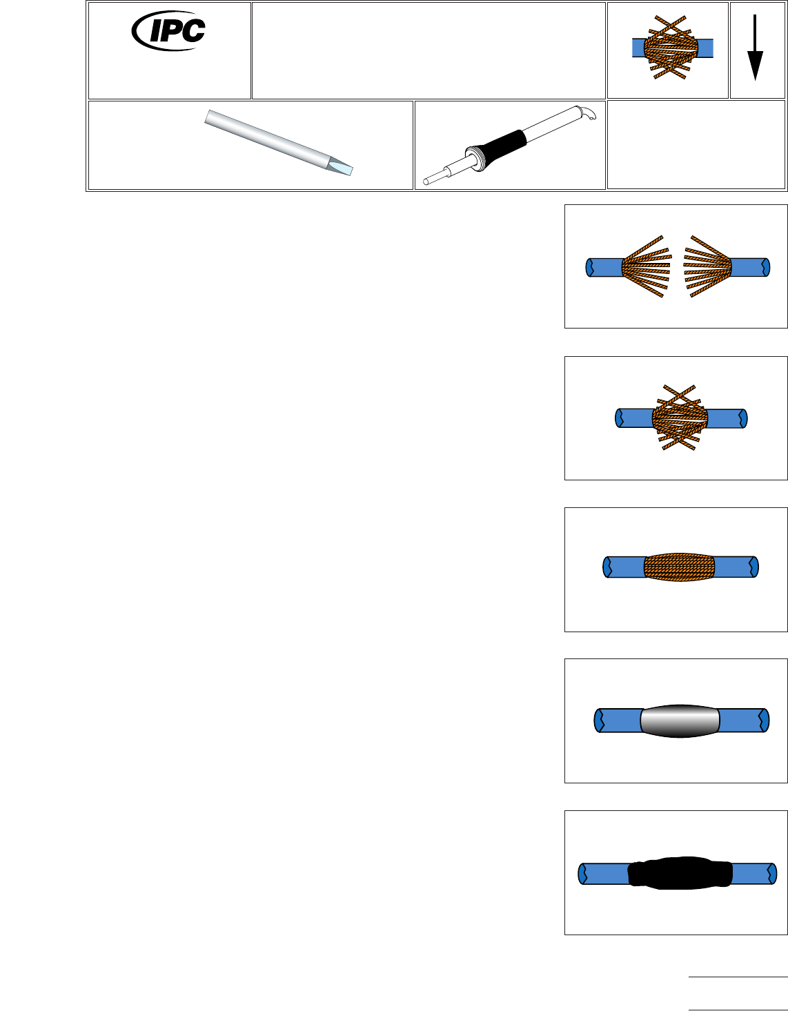
PROCEDURE
1. Install tip.
2. Start with tip temperature of approximately 260°C and change as necessary.
3. Form the mesh splice by fanning the wire strands on both untinned wires into a
cone shape. (See Figure 1.)
4. Gently begin meshing the wires together a minimum of 1.3 cm so that the strands
interlace evenly and of equal length. (See Figure 2.)
5. Twist the wires slowly using a slight pulling motion to restore the original lay of the
wire. Do not overtwist. (See Figure 3.)
WIRE SPLICING
6. Select appropriate heating element to establish a heat bridge and minimize the
effect of solder wicking beneath insulation. Solder in accordance with paragraph
8 in 8.1. (See Figure 4.)
NOTE
Flux contained in flux-cored solders should be sufficient to clean and solder splices.
If external flux is used, the chance of solder wicking beneath the insulation of
stranded wire is increased.
7. Clean, if required, and inspect.
8. Position insulation sleeve/tubing over the spliced area, apply heat to shrink to a
snug fit over the splice and wire insulation. (See Figure 5.)
Figure 1 Strip and Fan Wire Strands
Figure 2 Mesh Wire Strands
Figure 3 Smooth Down Strands
Figure 4 Solder Connections
Figure 5 Cover with Heat-Shrinkable
Tubing
7711A
Rework of
Electronic Assemblies
Revision:
Date: 2/98
Mesh Splice
Number: 8.1.1
Product Class: N/A
Skill Level: Intermediate
Level of Conformance: Low
Material in this manual, IPC-7711 Rework of Electronic Assemblies, was voluntarily established by Technical Committees of
IPC. This material is advisory only and its use or adaptation is entirely voluntary. IPC disclaims all liability of any kind as to the
use, application, or adaptation of this material. Users are also wholly responsible for protecting themselves against all claims
or liabilities for patent infringement. Equipment referenced is for the convenience of the user and does not imply endorsement
by IPC.
Page1of2
Copyright Association Connecting Electronics Industries
Provided by IHS under license with IPC
Not for Resale
No reproduction or networking permitted without license from IHS
--``,``,-`-`,,`,,`,`,,`---