IPC 7711A.pdf - 第314页
CAUTION The insulation shall not be stripped back more than two wire diameters from the solder joint. Wire insulation may touch but not penetrate the solder joint provided proper wetting of the wire is evident. 3. Bend t…

3. Remove solder from the connection point if needed. Clean the area.
4. Measure approximately the length of each wire needed.
JUMPER WIRE SELECTION
1. Bare conductor jumper wires longer than 12.7 mm [0.50 in] shall not be used.
Bare conductor jumper wires shorter than 12.7 mm [0.50 in] shall not violate the
minimum electrical clearance.
NOTE
The 12.7 mm [0.50 in] dimension refers to the length between terminations.
2. Silver plated wire must not be used; under some conditions corrosion of the wire
can occur.
3. The smallest diameter wire that will carry the required current should be selected.
4. Insulation requirements of the wire should withstand soldering temperatures, have
some resistance to abrasion, have a dielectric resistance equal to or better than
the board insulation material.
5. Recommended wire is solid insulated copper wire, tin lead plated, 22 to 32 AWG
with Kynar, Milene, Kapton, Teflon or equivalent insulation.
CAUTION
Wires with nicked or damaged conductors should not be used.
JUMPER WIRE PREPARATION
1. Cut the jumper wires approximately 12.7 mm [0.50 in] longer than the estimated
length needed.
NOTE
The length and gauge of the jumper wire may be critical. All wires have an elec-
trical resistance (impedance) to the flow of electricity. This impedance is important
to electronic circuitry. Always refer to wiring lists for specific jumper wire require-
ments.
2. Strip insulation from each end of the jumper wire.
NOTE
Strip length is dependent on the termination style.
3. If required, tin the stripped ends with solder. Clean if necessary.
JUMPER WIRE TERMINATING AND ROUTING
1. Form the wire as needed and place the wire in position depending on the termi-
nation style. Center the wire on the component lead or pad, do not overhang
sides. If the wire is soldered to a pin, terminal or component lead, wrap the wire
a minimum of 90°.
2. Solder one end of the wire. Clean if necessary.
NOTE
Solder joint length must meet acceptability requirements.
IPC-7721A
Number: 6.1
Revision:
Date: 11/99
Subject: Jumper Wires
Page3of10
Copyright Association Connecting Electronics Industries
Provided by IHS under license with IPC
Not for Resale
No reproduction or networking permitted without license from IHS
--``,``,-`-`,,`,,`,`,,`---

CAUTION
The insulation shall not be stripped back more than two wire diameters from the
solder joint. Wire insulation may touch but not penetrate the solder joint provided
proper wetting of the wire is evident.
3. Bend the wire as needed and run the wire along board surface. Route the jumper
wire using the shortest route in an XY direction with the fewest possible bends to
the second termination point.
NOTE
Jumper wires shall not be routed under or over component leads or component
bodies. Contact with heat sinks must be avoided.
CAUTION
Do not bend the wire tighter than a radius of three times the conductor diameter.
4. After routing the jumper wire, solder the opposite end. Clean if necessary.
CAUTION
Wires soldered to lifted or clipped components leads may require insulation to
prevent shorting.
JUMPER WIRE BONDING
1. After the wire has been soldered at both ends and cleaned if necessary, the wire
should be bonded to the board surface.
NOTE
Bonding is not required if wire is insulated and insulated length is less than 25 mm
[1.00 in].
2. Bond the jumper wire using one of the following methods.
A. Tape Dots or Tape Strips. (See Figure 4.)
B. Quick Set Adhesive. (See Figure 5.)
C. Hot Melt Adhesive. (See Figure 5.)
D. Hot Bonding. Some jumper wires are manufactured with a special thermo-set
adhesive coating and are thermally bonded to the board surface with a spe-
cial bonding tool. (See Figure 6.)
3. Bond the jumper wire within 6.0 mm [0.25 in] of each solder joint.
4. Bond the jumper wire within 6.0 mm [0.25 in] of each bend in the wire.
5. Bond the jumper wire at intervals not less than 25 mm [1.00 in] on straight runs.
IPC-7721A
Number: 6.1
Revision:
Date: 11/99
Subject: Jumper Wires
Page4of10
Copyright Association Connecting Electronics Industries
Provided by IHS under license with IPC
Not for Resale
No reproduction or networking permitted without license from IHS
--``,``,-`-`,,`,,`,`,,`---
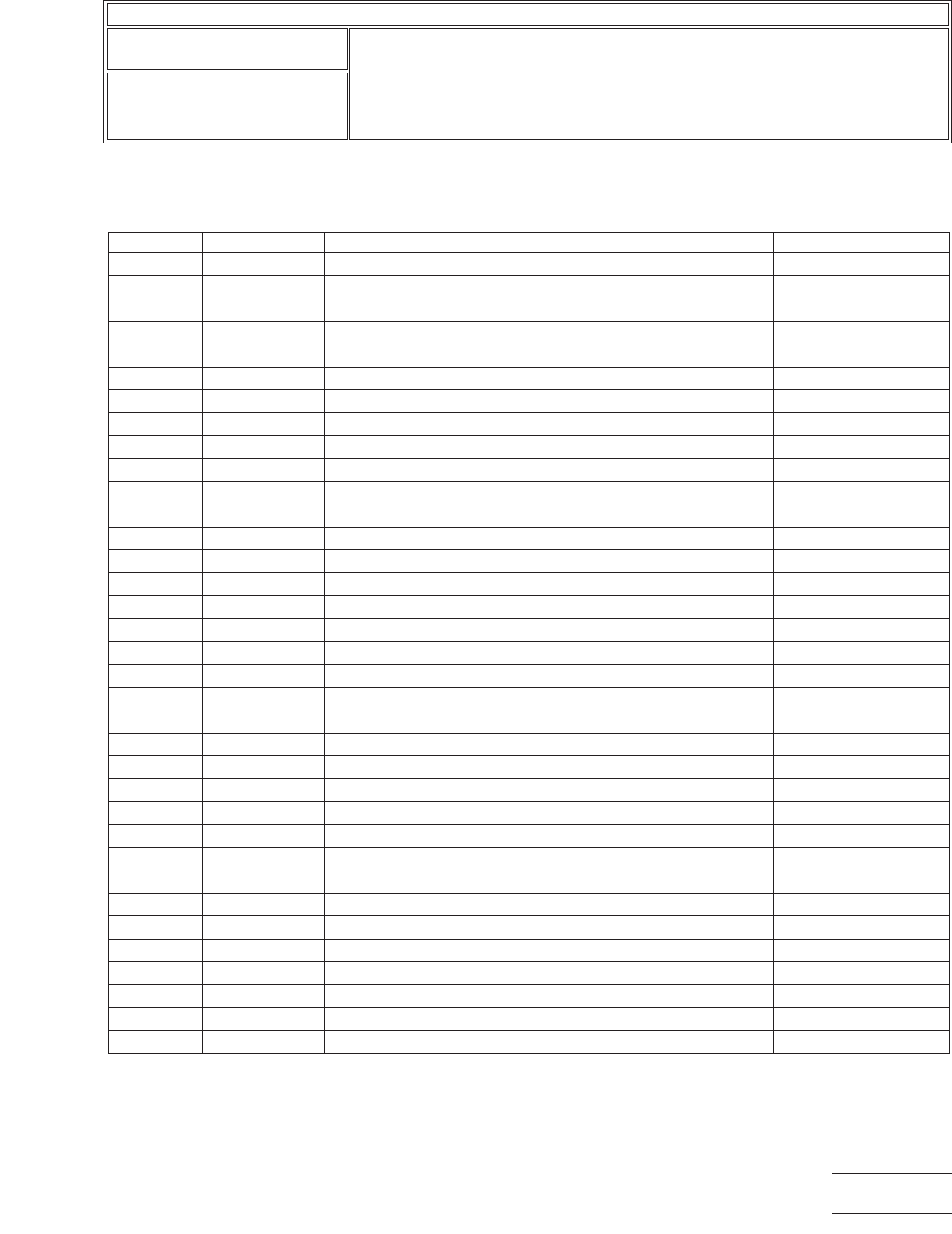
Table 1 Jumper Wire Termination Methods
Figure Type Wire Termination Method Acceptability
7 PTH Hole Wire soldered into plated-through hole on component side. * Acceptable
8 PTH Lead Wire soldered parallel to lead on component side. Acceptable
9 PTH Hole Wire soldered into plated-through hole on solder side. * Acceptable
10 PTH Hole Wire wrapped around component lead on solder side. Acceptable
11 PTH Hole Wire wrapped around lead on component side. Acceptable
12 PTH Lead Wire soldered to lifted component lead. + Acceptable
13 PTH Lead Wire soldered to clipped lead on component side. + Acceptable
14 PTH Lead Wire looped and soldered to adjacent component leads. Acceptable
15 PTH Lead Wire soldered to lead, wire over component. Not Recommended
16 PTH Lead Soldered perpendicular to component lead. Not Recommended
17 PTH Lead Multiple wires soldered to component lead overhanging edge. Not Recommended
18 Chip Wire soldered to pad, parallel or perpendicular to component. Acceptable
19 Chip Wire soldered parallel or perpendicular to component. Acceptable
20 Chip Wire soldered to component end, lifted off pad. Acceptable
21 Chip Multiple wires overhanging pad edge. Not Recommended
22 PTH Hole Wire soldered into plated-through hole. * Acceptable
23 PTH Pad Wire soldered across top of PTH pad. Acceptable
24 PTH Pad Multiple wires soldered to pad overhanging pad edge. Not Recommended
25 Conductor Wire soldered parallel to conductor, contact, SMT pad. Acceptable
26 Conductor Wire perpendicular to conductor, contact, SMT pad. Not Recommended
27 Conductor Multiple wires soldered to conductor, contact, SMT pad. Not Recommended
28 J Lead Wire soldered parallel to component lead. Acceptable
29 J Lead Wire soldered to clipped component lead. + Acceptable
30 J Lead Wire looped and soldered to adjacent component leads. Acceptable
31 J Lead Wire soldered to component lead, wire running over component. Not Recommended
32 J Lead Wire soldered perpendicular to lead. Not Recommended
33 J Lead Multiple wires soldered to lead overhanging edge. Not Recommended
34 J Lead Wire soldered to lifted component lead. Not Recommended
35 Gull Wing Wire soldered parallel to component lead. Acceptable
36 Gull Wing Wire soldered to lifted component lead. + Acceptable
37 Gull Wing Wire soldered to clipped component lead. + Acceptable
38 Gull Wing Wire looped and soldered to adjacent component leads. Acceptable
39 Gull Wing Wire soldered to component lead, wire over component. Not Recommended
40 Gull Wing Wire soldered perpendicular to component lead. Not Recommended
41 Gull Wing Multiple wires soldered to lead overhanging edge. Not Recommended
* Jumper wires soldered into plated-through holes must be discernible on the opposite side.
+ Jumper wires soldered to lifted or clipped component leads may require insulation to prevent shorting.
IPC-7721A
Number: 6.1
Revision:
Date: 11/99
Subject: Jumper Wires
Page5of10
Copyright Association Connecting Electronics Industries
Provided by IHS under license with IPC
Not for Resale
No reproduction or networking permitted without license from IHS
--``,``,-`-`,,`,,`,`,,`---