IPC 7711A.pdf - 第320页
This Page Intentionally Left Blank IPC-7721A Number: 6.1 Revision: Date: 11/99 Subject: Jumper Wires Page 10 of 10 Copyright Association Connecting Electronics Industries Provided by IHS under license with IPC Not for Re…
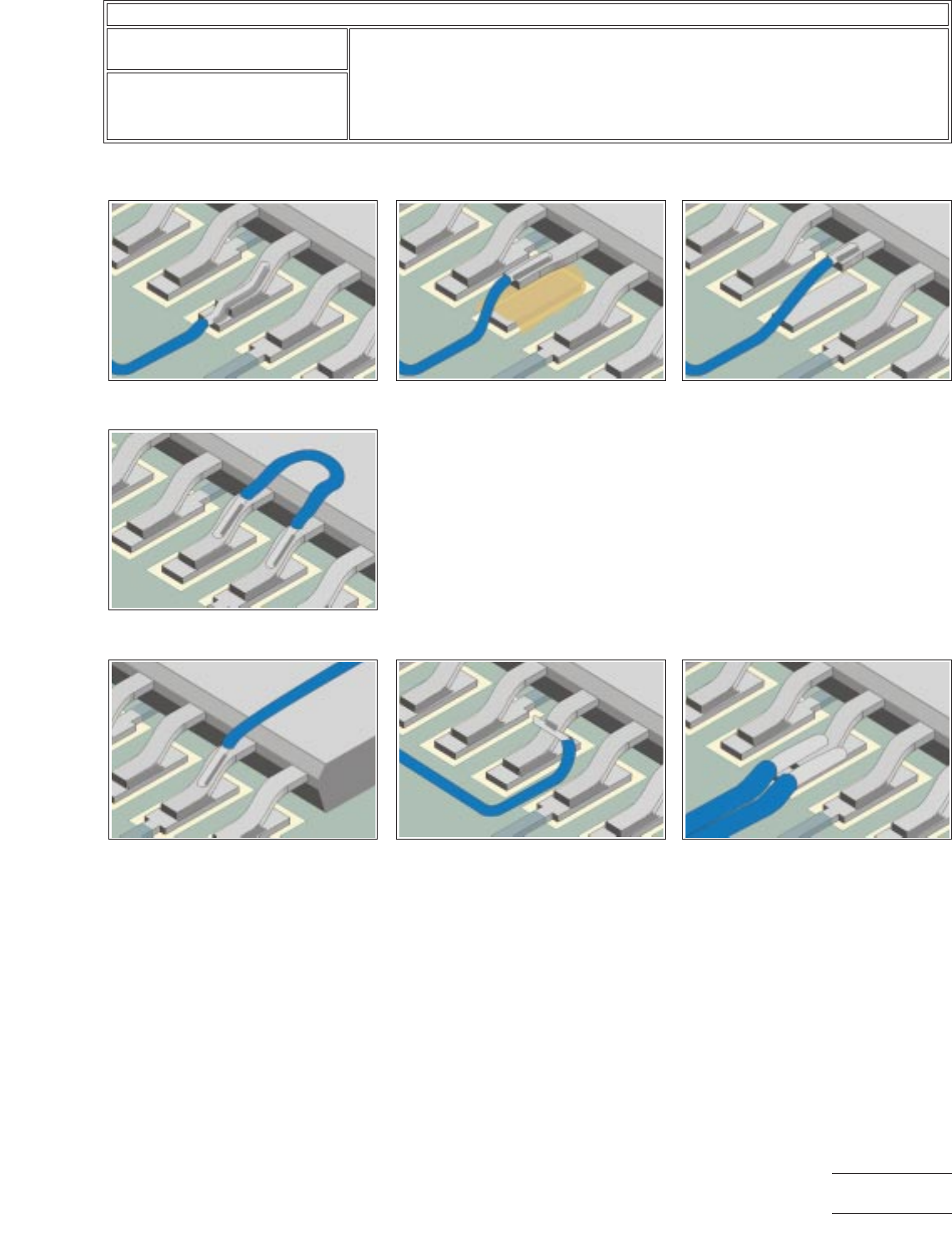
Jumper Wire Termination Figures – Gull Wing Components
* Jumper wires soldered into plated-through holes must be discernible on the opposite side.
+ Jumper wires soldered to lifted or clipped component leads may require insulation to prevent shorting.
Figure 35
Acceptable
Wire soldered
parallel to component lead.
Figure 38
Acceptable
Wire looped and
soldered to adjacent component leads.
Figure 39
Not Recommended
Wire sol-
dered to component lead, wire over component.
Figure 36
Acceptable
Wire soldered to
lifted component lead. +
Figure 40
Not Recommended
Wire
soldered perpendicular to component lead.
Figure 37
Acceptable
Wire soldered to
clipped component lead. +
Figure 41
Not Recommended
Multiple
wires soldered to lead overhanging edge.
IPC-7721A
Number: 6.1
Revision:
Date: 11/99
Subject: Jumper Wires
Page9of10
Copyright Association Connecting Electronics Industries
Provided by IHS under license with IPC
Not for Resale
No reproduction or networking permitted without license from IHS
--``,``,-`-`,,`,,`,`,,`---

This Page Intentionally Left Blank
IPC-7721A
Number: 6.1
Revision:
Date: 11/99
Subject: Jumper Wires
Page 10 of 10
Copyright Association Connecting Electronics Industries
Provided by IHS under license with IPC
Not for Resale
No reproduction or networking permitted without license from IHS
--``,``,-`-`,,`,,`,`,,`---
OUTLINE
This method is used to change a circuit path at a BGA site for engineering changes
or modifications.
NOTE
This procedure requires precision milling equipment and highly trained technicians.
CAUTION
This procedure is not applicable for ‘‘via in pad’’ applications.
REFERENCES
1.0 Foreword
2.1 Handling Electronic Assemblies
2.2 Cleaning
2.5 Baking And Preheating
2.6 Epoxy Mixing and Handling
4.2.1 Conductor Repair, Foil Jumper, Epoxy Method
4.4.3 Surface Mount, BGA Pad Repair, Film Adhesive Method
6.1 Jumper Wires
TOOLS & MATERIALS
BGA Rework System
Bonding Iron
Bonding Tips
Bonding System
Buffer
Circuit Frames, BGA Pads
Cleaner
Drill System
End Mills
Epoxy
Flux, Liquid
Foil Jumpers
Heat Lamp
Microscope
Milling System
Oven
Precision Knife
Repair System or Repair Kit
Scraper
Solder
Soldering Iron
Tape, High Temperature
Tweezers
Wipes
PROCEDURE
1. Clean the area.
2. Remove the BGA component if installed, remove excess solder from the pads,
and clean and inspect the site using standard BGA rework equipment.
3. Cut the short conductor (dog bone) connecting the BGA pad to the connecting
via using a drill system or milling machine and appropriate size end mill. (See Fig-
ure 1 and 6.)
4. Remove the existing BGA pad. Apply heat from a soldering iron if needed. (See
Figure 2.)
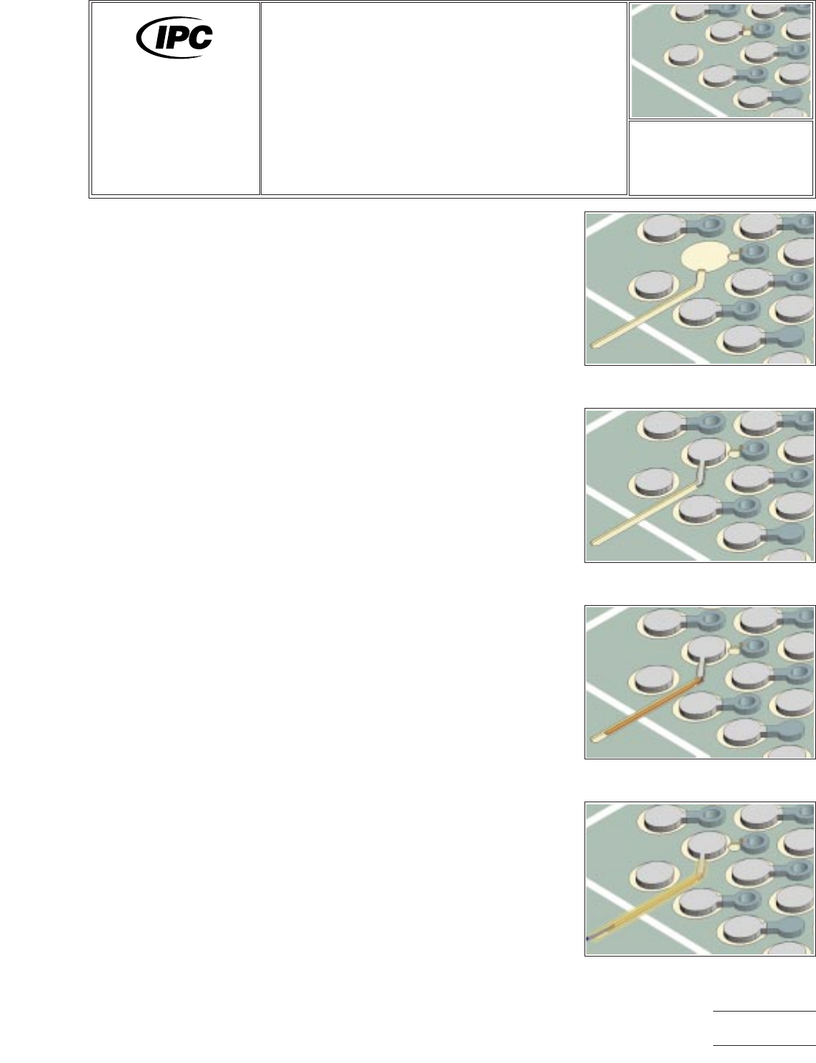
Figure 1 Cut the connection to the via
using a drill system.
Figure 2 Remove BGA pad & mill shal-
low channel into solder mask surface.
Figure 3 Bond a new BGA pad in
place.
Figure 4 Solder a foil jumper to the
tail extending from the new BGA pad.
7721A
Repair and
Modification of
Printed Boards and
Electronic Assemblies
Revision:
Date: 11/99
Jumper Wires, BGA
Components, Foil
Jumper Method
Number: 6.2.1
Product Class: R/F
Skill Level: Expert
Level of Conformance: Medium
Material in this manual was voluntarily established by Technical Committees of IPC. This material is advisory only and its use
or adaptation is entirely voluntary. IPC disclaims all liability of any kind as to the use, application, or adaptation of this material.
Users are also wholly responsible for protecting themselves against all claims or liabilities for patent infringement. Equipment
referenced is for the convenience of the user and does not imply endorsement by IPC.
Page1of2
Copyright Association Connecting Electronics Industries
Provided by IHS under license with IPC
Not for Resale
No reproduction or networking permitted without license from IHS
--``,``,-`-`,,`,,`,`,,`---