IPC 7711A.pdf - 第325页
EVALUATION 1. Visual examination for alignment and overlap of foil jumper. 2. Visual examination of epoxy coating for texture and color match. 3. Electrical tests as applicable. IPC-7721A Number: 6.2.2 Revision: Date: 10…
6. Select the appropriate size foil jumper. Cut a length approximately as needed.
The overlap solder connection should be a minimum of two times the circuit
width. (See Table 1.)
Table 1 Common Foil Jumper Sizes
Thickness Width
0.002’’ 0.004’’
0.002’’ 0.006’’
0.002’’ 0.008’’
0.002’’ 0.010’’
0.003’’ 0.120’’
0.003’’ 0.015’’
0.005’’ 0.020’’
0.005’’ 0.030’’
7. Gently abrade the top and bottom of the foil jumper with the buffer to remove
any oxidation and clean.
NOTE
If needed, the ends of the foil jumper may be tinned with solder prior to lap sol-
dering in place.
8. Insert an appropriately sized Teflon sleeve into the milled hole. This sleeve will
insulate foil jumper and prevent shorting to the inner layers. (See Figure 1.)
9. Insert one end of the foil jumper into the plated hole connected to the BGA pad.
Insert the opposite end through the Teflon sleeve. (See Figure 2.)
NOTE
Observe care to keep the Teflon sleeve in position while inserting the foil jumper.
10. Apply a small amount of liquid flux and solder the foil jumper to the plated hole
connected to the BGA pad using solder and a soldering iron. Make sure the foil
jumper is properly aligned. (See Figure 3.)
11. Clean the area.
12. Mix epoxy per appropriate procedure.
13. Coat the top and sides of the foil jumper with epoxy. The epoxy bonds the foil
jumper to the base board material and insulates it. (See Figure 4).
NOTE
Keep the epoxy height below the BGA pad level.
CAUTION
Some components may be sensitive to high temperature.
14. Clean the circuit board as required.
15. Install new BGA component per applicable procedures.
16. Solder a jumper wire to the exposed foil jumper on the opposite side of the cir-
cuit board. Route and terminate the jumper wire as needed.
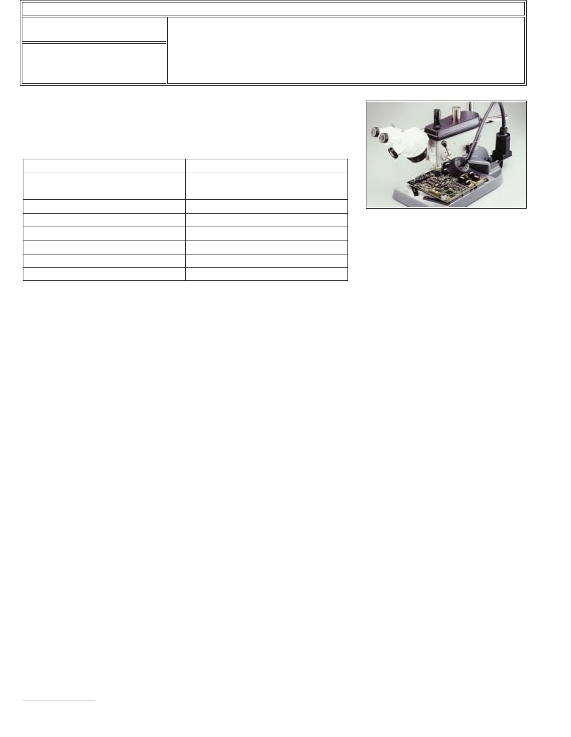
Figure 5 Precision Drill System used
for milling the Teflon sleeved hole.
IPC-7721A
Number: 6.2.2
Revision:
Date: 10/03
Subject: Jumper Wires, BGA Components, Through Board Method
Page2of4
Copyright Association Connecting Electronics Industries
Provided by IHS under license with IPC
Not for Resale
No reproduction or networking permitted without license from IHS
--``,``,-`-`,,`,,`,`,,`---

EVALUATION
1. Visual examination for alignment and overlap of foil jumper.
2. Visual examination of epoxy coating for texture and color match.
3. Electrical tests as applicable.
IPC-7721A
Number: 6.2.2
Revision:
Date: 10/03
Subject: Jumper Wires, BGA Components, Through Board Method
Page3of4
Copyright Association Connecting Electronics Industries
Provided by IHS under license with IPC
Not for Resale
No reproduction or networking permitted without license from IHS
--``,``,-`-`,,`,,`,`,,`---

NOTES
IPC-7721A
Number: 6.2.2
Revision:
Date: 10/03
Subject: Jumper Wires, BGA Components, Through Board Method
Page4of4
Copyright Association Connecting Electronics Industries
Provided by IHS under license with IPC
Not for Resale
No reproduction or networking permitted without license from IHS
--``,``,-`-`,,`,,`,`,,`---