IPC 7711A.pdf - 第329页
Component Modification Examples Figure 1 Radial lead component soldered to through hole component leads. Note: Leads of the radial component should not need to be inserted into the plated holes. Figure 2 Axial lead compo…

PROCEDURE
1. When required, form the component leads and clean the area.
2. When required, secure the component in place by bending leads or other
mechanical means.
3. Apply flux to the connection.
4. Place the soldering iron tip at the connection between both leads. Apply a small
amount of solder at the connection of soldering iron tip and lead to form a solder
bridge.
5. Immediately feed solder into the joint from the side opposite the soldering iron tip
until the proper fillet is achieved. Remove the solder and iron simultaneously.
6. When required, clean the flux residue.
7. Inspect.
IPC-7721A
Number: 6.3
Revision:
Date: 03/01
Subject: Component Modifications and Additions
Page2of4
Copyright Association Connecting Electronics Industries
Provided by IHS under license with IPC
Not for Resale
No reproduction or networking permitted without license from IHS
--``,``,-`-`,,`,,`,`,,`---
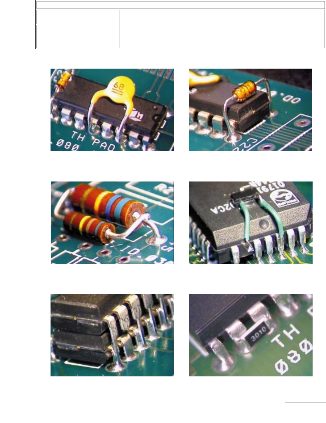
Component Modification Examples
Figure 1 Radial lead component soldered to
through hole component leads. Note: Leads of the
radial component should not need to be inserted
into the plated holes.
Figure 2 Axial lead component soldered to through
hole component leads. Note: Leads of axial
component should not be inserted into the plated
holes.
Figure 3 Axial lead component soldered to
adjacent axial lead component. Note: Added
component may be stacked vertically or
horizontally.
Figure 4 Chip component soldered to surface
mount component using jumper wires. Note: One
lead of surface mount component is shown lifted.
Figure 5 DIP component stacked and soldered
onto another DIP component. One lead shown
clipped. Note: Leads of added component should
not be inserted into the plated holes.
Figure 6 Chip cap bridging adjacent leads.
IPC-7721A
Number: 6.3
Revision:
Date: 03/01
Subject: Component Modifications and Additions
Page3of4
Copyright Association Connecting Electronics Industries
Provided by IHS under license with IPC
Not for Resale
No reproduction or networking permitted without license from IHS
--``,``,-`-`,,`,,`,`,,`---
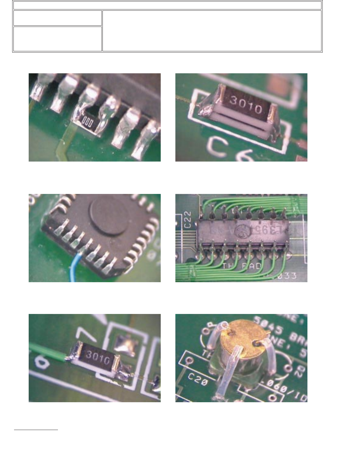
Component Modification Examples (continued)
Figure 7 Chip component bridging leads of surface
mount component.
Figure 8 Chip component stacked onto another chip
component.
Figure 9
Acceptable
Surface mount component
mounted upside down with jumper wires attached.
Note: One lead is bent outward.
Figure 10 DIP component mounted upside down with
jumper wires attached.
Figure 11 Chip component mounted to one pad only. Figure 12 Radial lead component mounted upside
down. Note: Insulate leads to avoid contact with
component body.
IPC-7721A
Number: 6.3
Revision:
Date: 03/01
Subject: Component Modifications and Additions
Page4of4
Copyright Association Connecting Electronics Industries
Provided by IHS under license with IPC
Not for Resale
No reproduction or networking permitted without license from IHS
--``,``,-`-`,,`,,`,`,,`---