IPC 7711A.pdf - 第333页
13. Clean replacement and form conductor in place. (See Figure 6 bottom.) CAUTION Avoid applying excessive heat to conductors. The laminate surrounding the repair area may melt. Place a wet lint-free tissue under the lam…
3. Remove the laminate around the damaged conductor by working on the thin-
nest side of the flexible conductor. Laminate can be removed by using a light
abrasive such as a pumice-impregnated wheel or rotary bristle brush. Removal
may also be accomplished by cutting with a scalpel or dental tool. (See Figure
1.)
NOTE
Placing the microscope at an angle of 10°-30° to the flexible laminate may aid
in determining the depth of the laminate removal.
4. Cut the laminate at a 45° angle along the bottom edge of the damaged con-
ductor. Ends of laminate should be cut out at a 90° angle perpendicular to the
conductor. The length of the laminate removed shall allow a minimum of 1/2
inch (1.3 cm) overlap on both sides of the damaged conductor area plus room
for the end fillets on both sides of the replacement conductor. (Laminate
Removal = Damaged Area + End Fillets + 1 inch (2.5 cm).) (See Figure 2.)
5. In many instances an adhesive will be coated onto the conductors. This must
also be removed from the area where the replacement conductor is going to
overlap the original conductor. The adhesive can be removed using light abra-
sion such as an ink eraser or rotary bristle brush or abrasive wheel. (See Figure
3.)
6. If conductor is not damaged and only the laminate requires replacement, pro-
ceed to step 18.
7. Once the laminate has been removed, the method of repair must be deter-
mined.
8. For a hairline crack, the repair will consist of a lap replacement with no original
conductor material removed. (See Figure 4.)
9. For more extensive damage, the damaged conductor will have to be removed
and a replacement conductor lap soldered in place. Any damaged portions of
the conductor shall be removed using the following method:
CAUTION
Exercise care when using a scalpel and tweezers to prevent damage to an
adjacent conductor.
10. Using a scalpel or dental chisel, bevel cut the conductor approximately 45° just
outside the damaged area on both sides. (In order to have at least 1/2 inch (1.3
cm) of original conductor exposed, additional laminate material may have to be
removed on both sides).
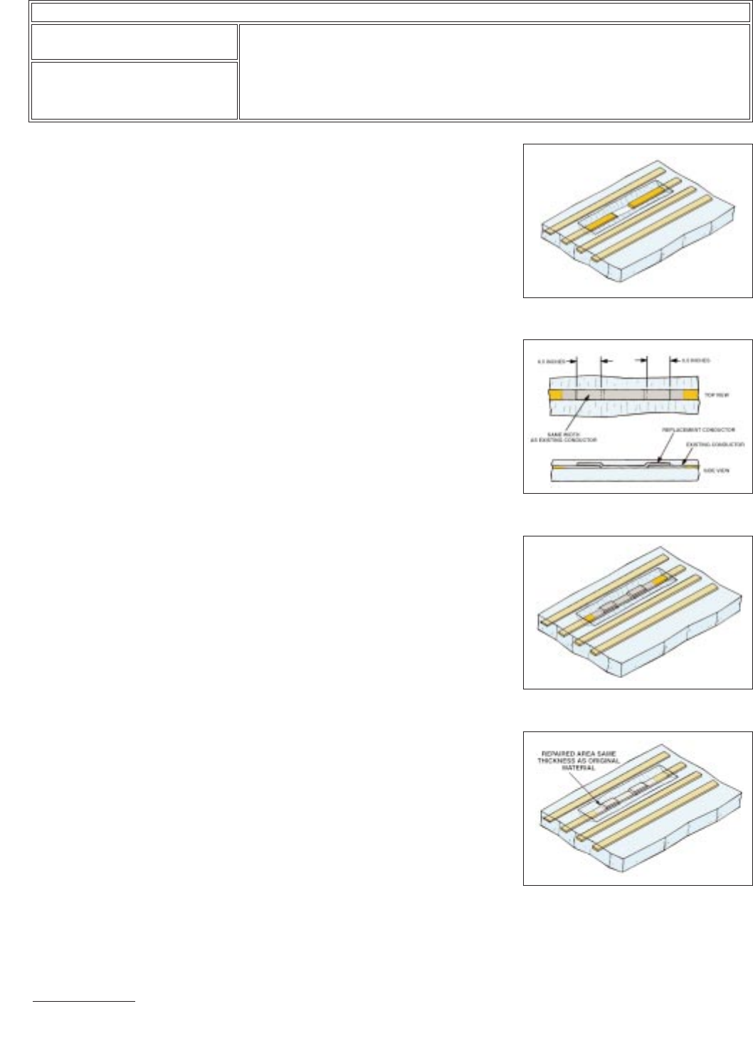
11. Grasp the damaged conductor with tweezers and remove. (See Figure 5.)
12. Obtain a replacement conductor equal to or slightly greater in width and thick-
ness and a minimum of 1 inch (2.5 cm) longer than the removed damaged con-
ductor. (See Figure 6 top.)
NOTE
All adhesive must be removed from the replacement conductor to ensure good
wetting action.
Figure 5 Beveling.
Figure 6 Replacement specifications.
Figure 7 Replacement conductor
soldered.
Figure 8 Repair encapsulated.
IPC-7721A
Number: 7.1.1
Revision:
Date: 10/03
Subject: Flexible Conductor Repair
Page2of4
Copyright Association Connecting Electronics Industries
Provided by IHS under license with IPC
Not for Resale
No reproduction or networking permitted without license from IHS
--``,``,-`-`,,`,,`,`,,`---

13. Clean replacement and form conductor in place. (See Figure 6 bottom.)
CAUTION
Avoid applying excessive heat to conductors. The laminate surrounding the
repair area may melt. Place a wet lint-free tissue under the laminate to help dis-
sipate heat while tinning and soldering the conductor.
14. Lightly tin the beveled ends and slightly beyond the overlap areas on each side
of the existing conductor.
15. Tin the bottom of the replacement conductor in the overlap areas. The replace-
ment conductor shall overlap the original area 1/2 inch (1.3 cm) minimum on
each side of the damaged area to allow for flexing of the circuit.
16. Position the replacement conductor and solder in place. Using extremely light
pressure with the soldering iron tip, follow along with a tool such as an orange-
wood stick, toothpick, or dental tool to hold the conductor down. (See Figure
7.)
17. After soldering, all flux residue must be removed with alcohol and a lint free tis-
sue or an acid brush.
CAUTION
Do not allow the alcohol to air dry, as it will leave a thin layer of flux residue.
18. After completing the conductor repair, the insulating layer of laminate that was
removed must be replaced. The most reliable method of laminate repair is to
reapply a thin coating of the same type used by the manufacturer. If the same
type of coating is not available, the following alternate procedures may be used.
19. To achieve reliable bonding of the coating, the laminate surface must be rough-
ened in the repair area with an abrasive cloth or ink eraser.
20. Clean the repair area thoroughly with alcohol.
21. Remove moisture by drying flexible printed wiring in a curing oven at 130°F
(54°C) for a minimum of one hour.
CAUTION
Read manufacturer’s warning labels and instructions. Follow all safety require-
ments and procedures while handling Silicone Resin.
22. Apply the coating with a dental tool to bring the level of the repair area to the
level of the original laminate. Feather the coating out on the sides of the repair
approximately 1/4 inch (0.64 cm). Air bubbles or voids should not exceed 25%
of the conductor spacing.
23. Cure following manufacturer’s specifications.
24. Clean the area with alcohol and an acid brush to remove any remaining debris
and residues. Inspect completed work.
25. If silicon adhesive is unavailable, polyimide tape may be used as a temporary
substitute.
IPC-7721A
Number: 7.1.1
Revision:
Date: 10/03
Subject: Flexible Conductor Repair
Page3of4
Copyright Association Connecting Electronics Industries
Provided by IHS under license with IPC
Not for Resale
No reproduction or networking permitted without license from IHS
--``,``,-`-`,,`,,`,`,,`---

26. Cut a piece of polyimide tape to cover both sides of the repair area. The size
should allow for a 1/4 inch (0.64 cm) overlap on the laminate. The overlap is
measured from the edge of the repair area. Round the corners of the tape with
a scalpel or scissors before applying tape to laminate. Do not stretch the tape.
CAUTION
Before applying polyimide tape, ensure that the assembly is free from all debris
and residues that would interfere with the polyimide tape bonding to the repair
area. Abrasion may be necessary if the surface of the laminate is slick and
smooth. Abrasion will promote greater adhesion of the replacement tape.
27. Place the polyimide tape, adhesive side next to the conductor, over the repair
area.
IPC-7721A
Number: 7.1.1
Revision:
Date: 10/03
Subject: Flexible Conductor Repair
Page4of4
Copyright Association Connecting Electronics Industries
Provided by IHS under license with IPC
Not for Resale
No reproduction or networking permitted without license from IHS
--``,``,-`-`,,`,,`,`,,`---