IPC 7711A.pdf - 第57页
EQUIPMENT REQUIRED Continuous vacuum desoldering system Desoldering tip Damp sponge OPTIONAL EQUIPMENT N/A MATERIALS Flux-cored solder Flux Cleaner Tissue/wipes PROCEDURE 1. Remove conformal coating (if any) and clean wo…

NOTE
For bubble free epoxy, remove the clip separating the resin and activator. Cut
open one end of the Epoxy tube and squeeze the contents into a mixing cup.
Slowly stir the mixture with the mixing stick. Be sure to stir the mixture for at least
2 minutes to ensure that all the resin and actuator have completely mixed.
3. If needed, add color agent to the mixed epoxy. Stir slowly to prevent bubbles.
CAUTION
Be sure the color agent is compatible with the epoxy mixture.
4. Apply or use as needed. (See Figure 2.)
5. Cure the epoxy per the manufacturer’s recommendations.
EVALUATION
1. Visual examination of epoxy for texture and color match.
2. Testing of epoxy surface for complete cure.
3. Electrical tests as applicable.
NOTES
IPC-7711A/7721A
Number: 2.6
Revision:
Date: 2/98
Subject: Epoxy Mixing and Handling
Page2of2
Copyright Association Connecting Electronics Industries
Provided by IHS under license with IPC
Not for Resale
No reproduction or networking permitted without license from IHS
--``,``,-`-`,,`,,`,`,,`---
EQUIPMENT REQUIRED
Continuous vacuum desoldering system
Desoldering tip
Damp sponge
OPTIONAL EQUIPMENT
N/A
MATERIALS
Flux-cored solder
Flux
Cleaner
Tissue/wipes
PROCEDURE
1. Remove conformal coating (if any) and clean work area of any contamination,
oxides, residues or fluxes.
2. Install thermal drive desoldering tip handpiece.
3. Start with tip temperature of approximately 315°C and change as necessary.
4. Apply flux to all solder connections (optional).
5. Thermal shock tip with damp sponge.
6. Tin tip with solder.
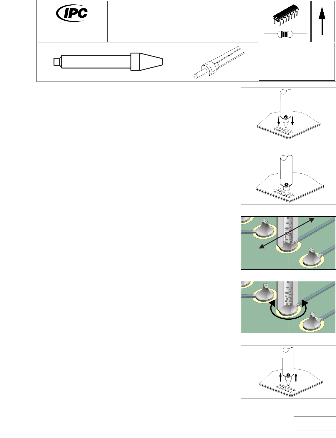
7. Lower tip contacting solder connection. (See Figure 1.)
8. Confirm complete solder melt of contacted lead. (See Figure 2.)
NOTE
Auxiliary heating may be required on solder joints with a large thermal mass.
This is most common on multilayer PC boards.
9. For a flat lead, move lead back and forth; for a round lead, use a circular motion
and apply vacuum while continuing lead movement. (See Figures3&4.)
10. Lift tip from lead, hold vacuum for sufficient time to clear all molten solder from
heater chamber. (See Figure 5.)
11. Repeat for all solder connections.
12. Re-tin tip end with solder and return handpiece to its stand.
13. Clean lands as required for component replacement.
Figure 1 Position Tip
Figure 2 Melt Solder
Figure 3 Move Lead & Apply Vacuum
Flat Lead
Figure 5 Lift Handpiece
Figure 4 Move Lead & Apply Vacuum
Round Lead
7711A
Rework of
Electronic Assemblies
Revision: A
Date: 5/02
Through-Hole Desoldering
Continuous Vacuum Method
Number: 3.1.1
Product Class: R, F, W
Skill Level: Intermediate
Level of Conformance: High
Material in this manual, IPC-7711 Rework of Electronic Assemblies, was voluntarily established by Technical Committees of
IPC. This material is advisory only and its use or adaptation is entirely voluntary. IPC disclaims all liability of any kind as to the
use, application, or adaptation of this material. Users are also wholly responsible for protecting themselves against all claims
or liabilities for patent infringement. Equipment referenced is for the convenience of the user and does not imply endorsement
by IPC.
Page1of2
Copyright Association Connecting Electronics Industries
Provided by IHS under license with IPC
Not for Resale
No reproduction or networking permitted without license from IHS
--``,``,-`-`,,`,,`,`,,`---

NOTES
IPC-7711A
Number: 3.1.1
Revision: A
Date: 5/02
Subject: Through-Hole Desoldering
Page2of2
Copyright Association Connecting Electronics Industries
Provided by IHS under license with IPC
Not for Resale
No reproduction or networking permitted without license from IHS
--``,``,-`-`,,`,,`,`,,`---