circuit of HS60.pdf - 第102页
3 - 7 0033615 2-030 103LD3 Distrib utor , secto r 1 (Sh. 1 of 2) 3 5 2 4 6 1 GND +5V +24V Voltages r ing circu it Sec4<>Sec1 Voltages r ing circu it Sec1<>Sec2 Infeed Socket 1, per iph eral modul es Start Sto…
3 - 6
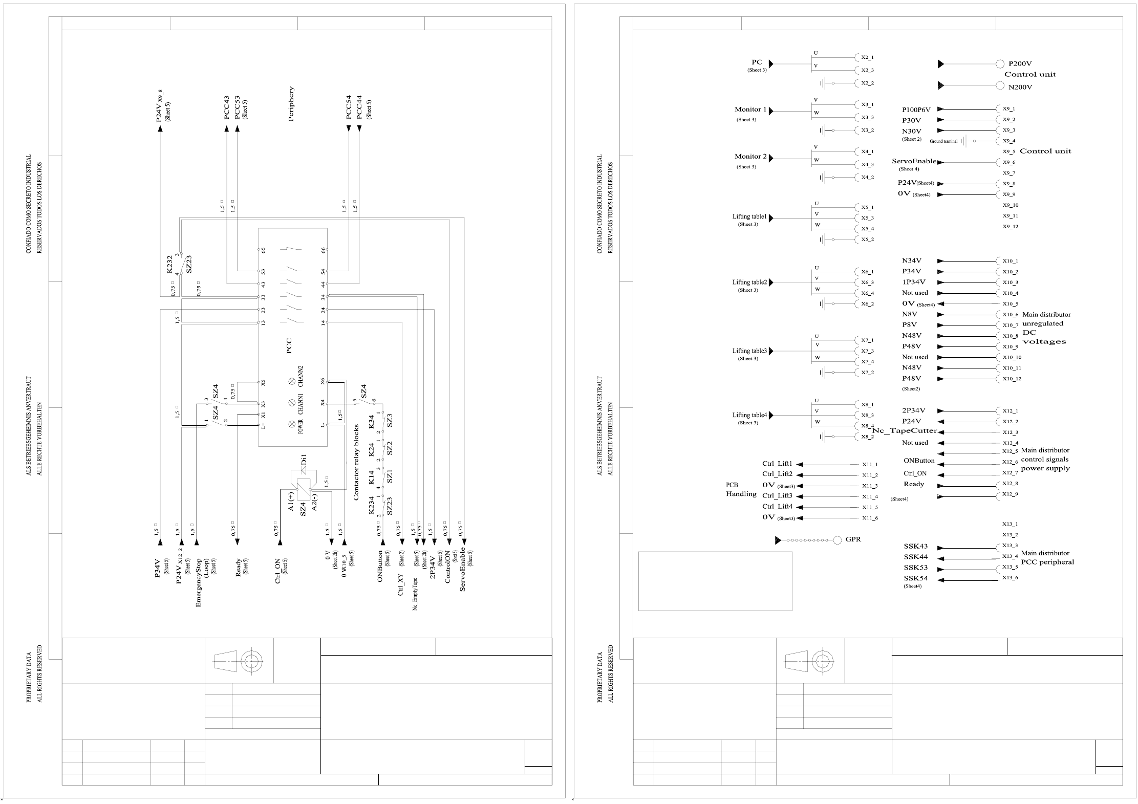
00336145-030201LD4 HS60 circuit diagram with option lifting table (dual conveyor) (Sh. 5 of 6)
00336145-030201LD4 HS60 circuit diagram with option lifting table (dual conveyor) (Sh. 6 of 6)
Sheet 4
1234
D
C
B
A
E
SIEMENS
A&D CD TDV Bremen
TEF3
Willnecker
Cramer
00336145-030201LD4
Typ 4AV1301-4CT-1D
AutoCAD
5
6
with option lifting table (dual conveyor)
HS60 power supply
(NC)(NC)(NO)(NC)
Cutter
29.6.99
Technical aspects Untol. dimens. Scale: Weight:
Check.
Stand.
Date
Author
ModifiedStat. NameDate Replacement for Replaced by
Sheet
Sh.
EmergencyStop
ControlOn
Ground terminal
Ground terminal
Ground terminal
Ground terminal
Ground terminal
Ground terminal
Ground terminal
Ground terminals
29.6.99
P200V
P100P6V
P30V
P34V, 2P34V
P8V
P48V
=
=
=
=
=
=
approx. 200V
approx. 100V/ 4V
approx. 30V
approx. 40V
approx. 10V
approx. 52V
Voltage ratings in the circuit diagrams correspond to signal names.
Please refer to the table above for the real voltages and their corresponding signal names.
Technical aspects Untol. dimens. Scale: Weight:
Check.
Stand.
Date
Author
ModifiedStat. NameDate Replacement for Replaced by
Sheet
Sh.
(Threaded bolt
M10)
(Threaded bolt
M8)
Sheet 5
1234
D
C
B
A
E
SIEMENS
A&D CD TDV Bremen
TEF3
Willnecker
Cramer
00336145-030201LD4
Typ 4AV1301-4CT-1D
AutoCAD
6
6
with option lifting table (dual conveyor)
HS60 power supply
Threaded bolt M6
3 - 7
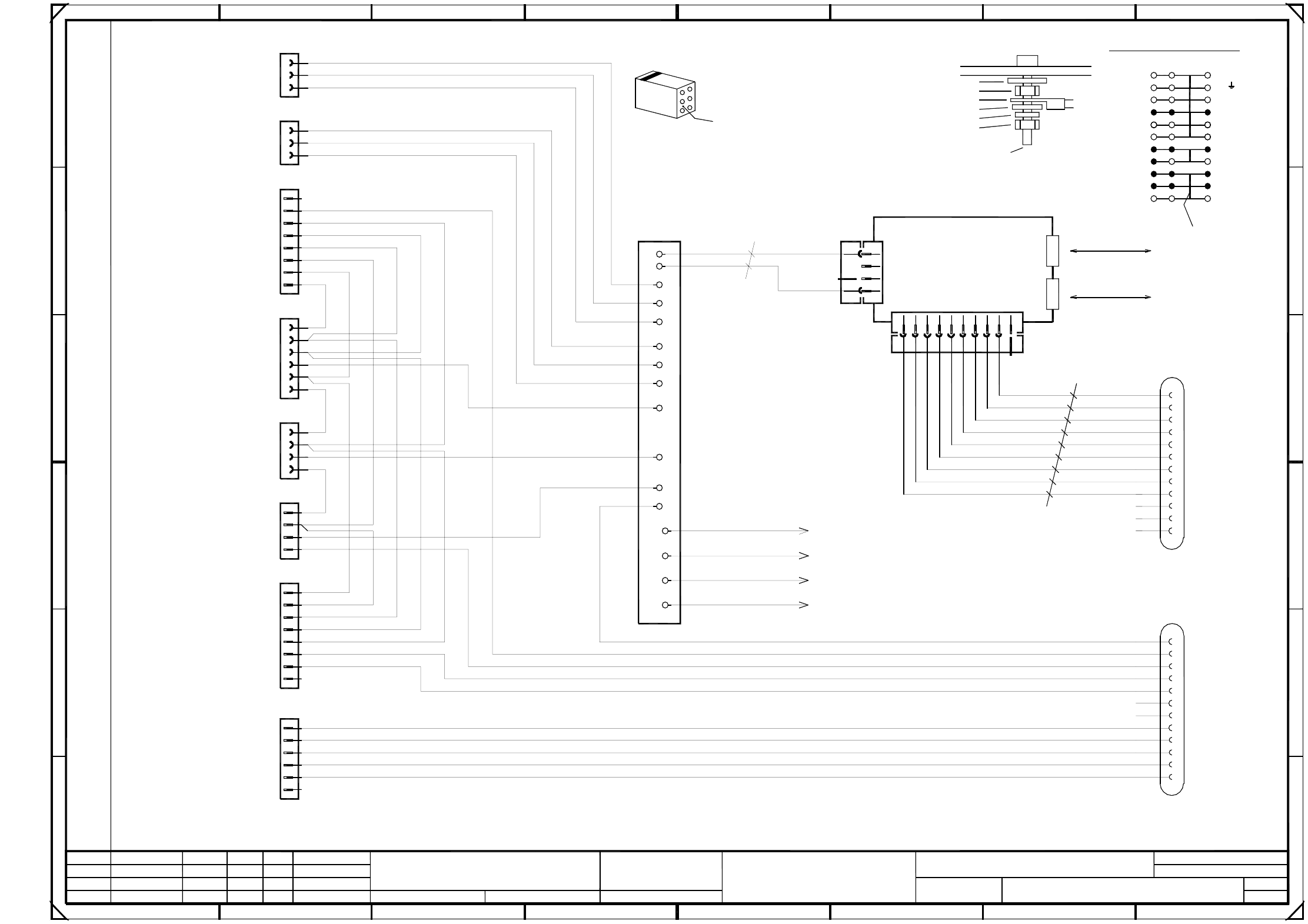
00336152-030103LD3 Distributor, sector 1 (Sh. 1 of 2)
3
5
2
4
6
1
GND
+5V
+24V
Voltages ring circuit
Sec4<>Sec1
Voltages ring circuit
Sec1<>Sec2
Infeed
Socket 1, peripheral modules
StartStopInputRight
Emerg.StopPCBInput
Safety ring circuit
Sec4<>Sec1
Safety ring circuit
Sec1<>Sec2
5
B
SMD Placement System SIPLACE HS60
4
X1af
A7
A10
+24V
+24V
1P34V
P8V
N8V/34V
GND
+5V
+24V
876
D
2
X3ag and X4ag ,
X100 terminals overview
X5af
X2af
X8af
X4af
X6af
X3af
Hood1
All control lines: 1.00mm² / black
Cable ties are used to form the cable harness !
+24V
X25af
CompFlap1
X7af
2
F
A module
M5 split washer, DIN 7980
M5x16 fillister head screw, DIN 912
M5 hexagon nut, DIN 439
Distributor sheet
Locking clip plug:
To Harting plug housing (from X1)
PE
A11
N8V/34V
6
1
P8V
32
C
+5V
CAN_INT
CAN_RESET
GND
+5V
GND
A
Ground connection :
Contact washer
M5 hexagon nut, DIN 439
Annular cable lug
B5
B6
B9
B8
B7
10
B module
CANL
CANH
3
4
5
76
X3ag
X4ag
B10
B11
B12
B2
34
A6
+5V
C
A3
A8
A4
E
gnye
00336788gnye
00336789gnye
00336790
PE
PE
8
B
5
1
D
1
A9
A1
A2
X3ag
X2ag
M5 washer, DIN 125
X1ag
500kbps
CAN bus
500kbps
X5ar - X16ar
B4
key
key
B1
A5
A
8
A12
2
3
CAN bus
1P34V
To cover
To distributor sheet
To machine frame
0.56mm² / bk
Bridge
A1 CAN-bus coupler
00332557 (ag)
0.56mm² / bk
00336787
X100
7
ab c
GND
F
03.
01.
03.
Tek
Tek
Tek
2
gnye
B3
+24V
X1af
GND
X4ag
E
4b
1a
2c
4c
109
24.03.99
1
00336152-030103LD3
Distributor, sector 1
Hoffmann
11.12.1997
10.04.00
24.03.99
Document stat.
Product stat.
Function stat.
3
5
4
1
2
3
6
6
7
4
5
3
1
2
8 / 9
4
2
1
2
3
4
PE
PE
5
4
6
7
1
3
PL EA1 E2
5
1
1
3
6
2
4
1
3
2
2
8 / 9
1
2
3
1
2
3
4
5
8
8
29
must be as viewed from the rear side of the casing.
Cable
GROUND
7
PE
6a
7a
7b
7c
3c
that the numerical sequence of a locking clip plug
Please note that ...
4a
PE
16
71
1
5
4
4
3
3
2
6
6c
2a
4
Spare
Spare
Spare
Address bit 1
GND_Address
Address bit 0
S_Begin
L_Begin
L_End
S_End
Spare
Spare
PCC11
PCC12
ModifiedStatus Stand.Date Name
Orig. Replaced byRepl. f.
Author
Check.
Date
Spare
S_CompEnd
S_hood
S_StartButton
S_Emerg.StopButton
S_CompFlap
S_StopButton
L_End
L_Begin
S_Emerg.StopButton
S_StartButton
S_StopButton
L_End
L_Begin
S_hood
L_End
L_Begin
S_CompFlap
L_End
S_StopButton
S_CompFlap
S_Emerg.StopButton
S_StartButton
S_hood
L_End
S_CompEnd
Spare
PCC11
PCC12
Spare
Sheet
Sh.
=
SIEMENS AG
+
3 - 8
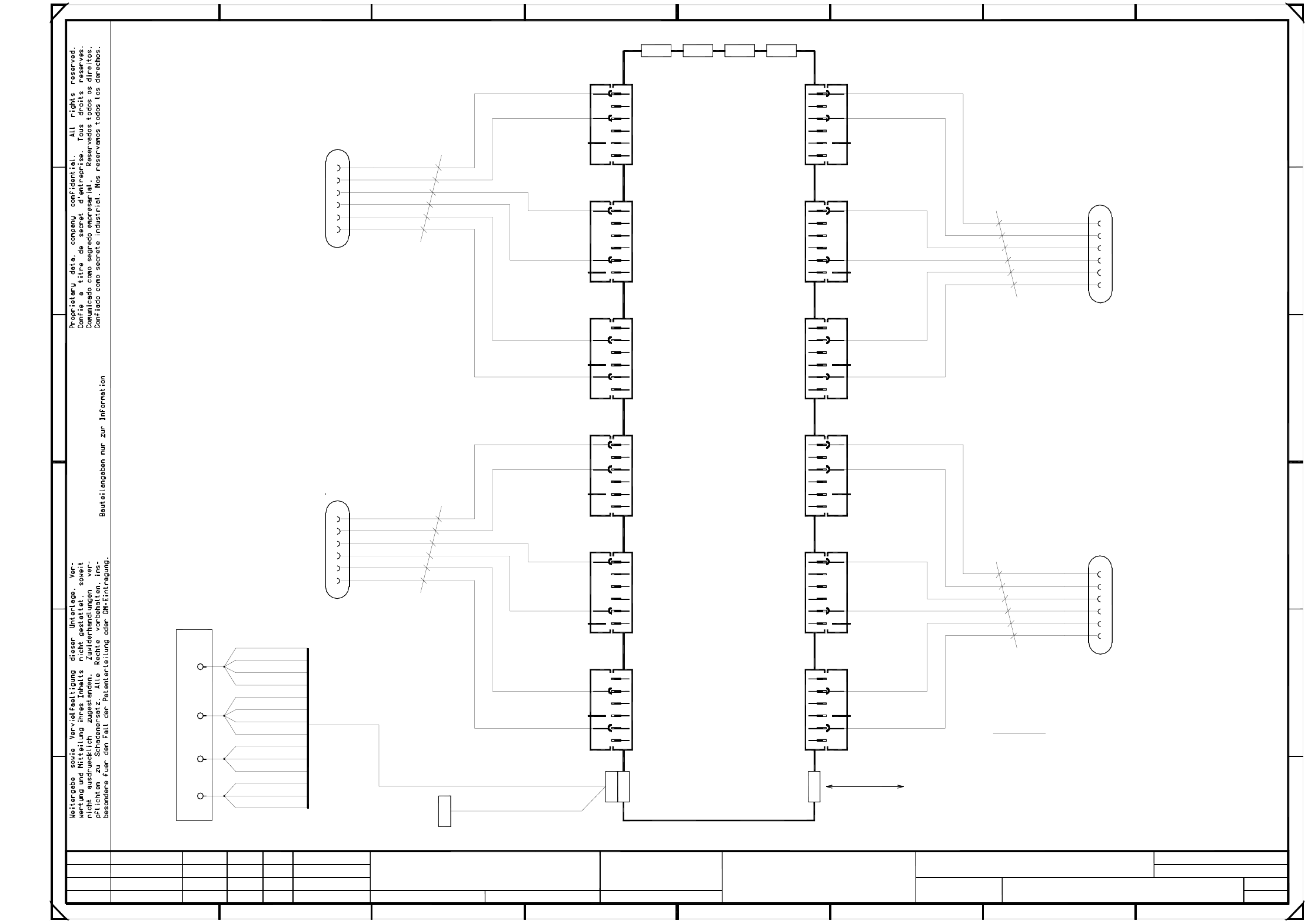
00336152-030103LD3 Distributor, sector 1 (Sh. 2 of 2)
4
5
6
2
3
4
6
0.56mm² / bk
X17*
+24V
GND
X9arX9ar
has been hard wired; installed as option only!
CAN input/output module 3 (A2)
E
A
1
6
0V
0V
X8ar
0V
0V
E
X16ar
CAN input/output module 3
4
3
X7arX7ar
key
0.56mm² / bk
GND
E
E
4
X14ar
E
key
Nozzle changer 4b
0.56mm² / bk
+24V
GND
+5V
GND
Not
24V
24V
0V
0V
X13ar
X100
1
2
A
X10arX10ar
A
E
+24V
4
3
24V
24V
0V
0V
1
6
A
24V
24V
0V
0V
X12ar
key
key
24V
0V
0V
+24V
X11ar
X12ar
X13ar
X14ar
E
A
24V
24V
0V
24V
24V
0V
6
2
F
678
key
connected
CAN bus
125kbps
X5ar
key
24V
24V
E
0V
SMD Placement System SIPLACE HS60
A
3
4
A2
6
0.56mm² / bk
Please note !
0V
14
00336801
X17ar
0V
X11ar
key
E
GND
GND
Nozzle changer 1b
0V
10.04.00
11.12.1997
Hoffmann
Distributor, sector 1
00336152-030103LD3
2
24.03.99
X1ar is reserved for the "Fill level" monitoring
Reserved
GND
X1ar X2ar
6
2
4
5
6
0V
X6ar X6ar
E
A
Nozzle changer 3b
key
2
5
3
2
2
Tek
Tek
Tek
03.
01.
03.
Function stat.
Product stat.
Document stat.
24.03.99
PL EA1 E2
6
5
5
5
1
X18af
1
2
3
4
5
6
3
X17af
1
2
3
4
5
6
2
1
2
1
4
5
6
5
6
1
2
3
5a
1
1
6
1
2
3
4
5
6
3
4
5
6
1
2
3
5
1
5
4
4
5
6
1
2
3
4
5
6
1
3
4
5
6
3
4
5
6
1
2
3
4
5
6
1
2
3
4
5
6
2
3
1b
1c
1
5
2
5
1
3
1
5
2
6
X19af
1
2
3
4
5
6
6b
1
1
X20af
1
2
3
4
5
1
2
3
4
1
2
3
4
5
3
2
S_LeftNozzles(open)
S_RightNozzles(closed)
Ctrl_ValveNozzles
S_LeftNozzles(open)
S_RightNozzles(closed)
Ctrl_ValveNozzles
Stand.Status NameDateModified
Orig. Repl. f. Replaced by
Date
Check.
Author
Sheet
Sh.
S_LeftNozzles(open)
S_RightNozzles(closed)
Ctrl_ValveNozzles
Ctrl_ValveNozzles
S_LeftNozzles(open)
S_RightNozzles(closed)
1
6
2
4
5
E
A
24V
24V
0V
0V
5
A
B
567
2
2
D
C
0V
0V
X3ar
E
A
24V
24V
0V
2
B
F
E
=
SIEMENS AG
+
D
C
10
11
12
13
24V
24V
A
X15ar
8
X18ar
X17ar
X16ar
2
4
5
6
1 4
3
4
6
1
3
4
GND
32
X4ar
24V
E
A
24V
key
X8ar
A
key
key
key
+24V
Nozzle changer 2b
3
4
5
6
7
A
24V
24V
3
4
6
1
3
4
8
9
00329698 (ar)
GND
X15ar
GND
X5ar
24V
23