circuit of HS60.pdf - 第117页
4 - ii SIPLACE HS-60 Det ailed Circuit Diagrams Folder 03/2003 US Editi on
SIPLACE HS-60 Detailed Circuit Diagrams Folder
03/2003 US Edition
4 - i
4 Assemblies - Overview Diagrams
00334808-020301TD3 HS-60 control unit, viewed from the front 4 - 1
00334809-010401TD3 HS-60 control unit without boards, viewed from the front (Sh. 1 of 2) 4 - 2
00334809-010401TD3 HS-60 control unit without boards, viewed from the back (Sh. 2 of 2) 4 - 3
00334810-020103TD3 HS-60 servo unit, viewed from the front (Sh. 1 of 2) 4 - 4
00334810-020103TD3 HS-60 servo unit, viewed from the front (Sh. 2 of 2) 4 - 5
00335891-010202TD3 HS60 servo unit without boards, viewed fron the front (Sh. 1 of 2) 4 - 6
00335891-010202TD3 HS60 servo unit without boards, viewed fron the back (Sh. 2 of 2) 4 - 7
00335897-010102TD3 HS60 potential distributor 4 - 8
00336152-030103TD3 Distributor, sector 1 4 - 9
00336153-030301TD3 Distributor, sector 4 4 - 10
00336154-020201TD3 HS60 main distributor 4 - 11
00336181-030103TD3 Distributor, sector 2 4 - 12
00336182-030103TD3 Distributor, sector 3 4 - 13
4 - ii
SIPLACE HS-60 Detailed Circuit Diagrams Folder
03/2003 US Edition
4 - 1
4 Assemblies - Overview Diagrams
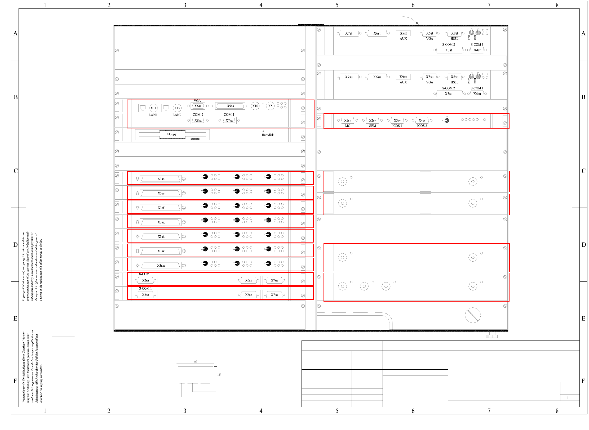
00334808-020301TD3 HS-60 control unit, viewed from the front
(tc)
(te)
(td)
(tb)
(ta)
(sv)
(su)
(st)
(so)
(sn)
(sm)
(sk)
(sh)
(sg)
(sf)
(se)
(sd)
(sa)
(sb)
(ss)
(sr)
SIEMENS SD EA
00334808 / FS
AA-BBBB-CCCC
+ 52V
+ 5V
- 15 V
+ 15 V
+ 12 V
- 12 V
Servo
Aus
Aus
Servo
Aus
Servo
Servo
Aus
Servo
Aus
Aus
Servo
Servo
Aus
Servo
Aus
Aus
Servo
Servo
Aus
Aus
Servo
Aus
Servo
Servo
Aus
Servo
Aus
Aus
Servo
Servo
Aus
Servo
Aus
Aus
Servo
Servo
Aus
Aus
Servo
Aus
Servo
+ 5 V
+ 24 V
A31:2
02.
10.09.1997 Hoffmann
27.07.01
27.07.01
27.07.01
Tek
Tek
Tek
03.
01.
00334808-020301TD3
SD EA
SIEMENS
Stamm-Nr. FS ES US UAS F
Function stat.
Product stat.
Document stat.
ModifiedStatus Date Name
Scale
Author
Check.
Stand.
Date
Name
Sheet(Drawing number)
Sh.
HS60 control unit
( viewed from the front )
Reserved for
GEM machine controller
Winchester/floppy, GEM
Reserved for PCI
Reserved for PCI
Reserved for
A15 assembly
A16 assembly
Axis card 5
Diagnosis
Communication assembly 1
Communication assembly 2
A10 assembly
A11 assembly
A12 assembly
Axis card 6
A8 assembly
A9 assembly
Axis card 7
Axis card 3 x AC 4
Axis card 3 x AC 2
Axis card 3 x AC 3
Axis card 3 x AC 1
A6 assembly
A7 assembly
A4 assembly
A5 assembly
Winchester/M54 floppy
Machine controller
A2 assembly
Spare
Spare
A1 assembly
Apply the following labels on the outside (flush with the front plate):
A: identification label
* Please note
Font size 2.5mm, material Scotchal 3698-E (Color Al RAL 9006)
Assembly inscription acc. to VA-F-510-001
Manufacturer/location acc. to SN 37040
Date (year/month/day) acc. to SN 01007
Series number
B: inspection label Identification: testing engineer, month, year
CAN bus CAN bus
CAN busCAN bus
Fan unit
Keyboard
Mouse
Printer
* Please note
Camera 2/4 Camera 1/3
Camera 2/4 Camera 1/3
Video multiplexer
A19 assembly
Power supply unit +/- 12V
A20 assembly
Power supply unit +/- 15V
A21 assembly
Spare
Spare
Spare
Gantry 2/3
Gantry 1/4
Vision system MVS340 (ICOS 1)
A17 assembly
Vision system MVS340 (ICOS 2)
A18 assembly
A22 assembly
Power supply unit +5V / +24V
A23 assembly
Power supply unit +5V
A24 assembly
Power supply unit +5V / +3,3V
Reserved for
Battery
3.8V
SMD Placement System SIPLACE HS60
see page 5-16
See page 5-16
See page 5-16
See page 5-16
See page 5-16
See page 5-16
See page 5-16
See page 5-31
See page 5-31
See page 5-12
See page 5-3
See page 5-6
See page 5-4
See page 5-5
See page 5-19