circuit of HS60.pdf - 第146页
5 - 14 0033541 3-020 101ND 3 830 board, potenti al distr ibutor HS-60 BR4 Jump er in serte d BR 5 Not in sert ed BR6 Open BR7 Jump er in serte d BR8 Jump er in serte d BR 9 Not in sert ed BR10 Not ins er ted BR11 Not ins…
5 - 13
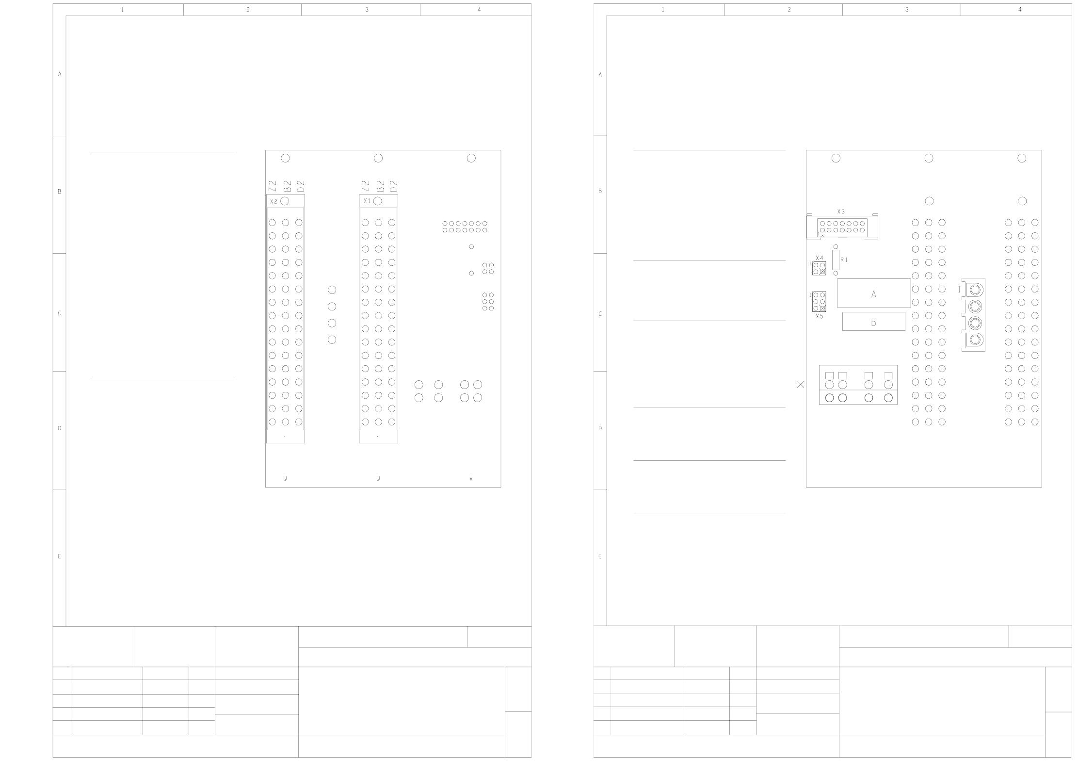
00333635-010201ND4 836 board, backplane AC 12,5 (Sh. 1 of 2)
00333635-010201ND4 836 board, backplane AC 12,5 (Sh. 2 of 2)
Stat. Modified Date Name
Date
Name
Scale 1:1
Sheet
Sh.
03
10.12.98 KL
X1
D4
Z4
B6
D6
D8
D12
Z12
D14
D16
D/B/Z18
D/B/Z20
D/B/Z22
D/B/Z24
D/B/Z26
D/B/Z28
D/B/Z30
D/B/Z32
Servo Enable
Link voltage
Link voltage
PHASE_V
PHASE_W
PHASE_U
PHASE_V
GND
GND
I²t
Servo Ready
Brake-
Inom-W
Inom-U
Brake +
+15V
-15V
X2
B2
Z2
D/B/Z18
D/B/Z20
D/B/Z22
D/B/Z24
D/B/Z26
D/B/Z28
D/B/Z30
D/B/Z32
PHASE_U
PHASE_W
PHASE_V
PHASE_V
MOTOR_V
MOTOR_U
MOTOR_W
Brake +
Brake -
GND
G32918-J0018-B001-*-0017
2-layer printed circuit board
Mounting diagram, component side
836 board
AC 12.5 backplane
00333635-010201ND4
2
1
SIEMENS AG
10.12.98
Goller
22.07.97
25.11.97
30.06.97
KL
KL
KL01
02
03
Enable
5
10
4
3
1, 8, 9, 13, 14
2, 6
X3
n.u.
Inom - W12
3
2
1
X4
GND
Tacho -
Tacho +
2
1
X5
3 Crash signal
Tacho +
Tacho -
4 + 15 V
5n.u.
X6
1, 3
2, 4 - 15 V
+ 15 V
2, 4
1, 3
X7
GND
Link voltage
2
3
4
1
X8
MOTOR_W
MOTOR_V
MOTOR_U
GND
Socket
= pinch off key pin
G32918-J0018-B001-*-0017
2-layer printed circuit board
Mounting diagram, solder side
836 board
AC 12.5 backplane
00333635-010201ND4
2
2
SIEMENS AG
10.12.98
Goller
22.07.97
25.11.97
30.06.97
KL
KL
KL01
02
03
B = inspection label
A = identification label
Stat. Modified Date Name
Date
Name
Scale 1:1
Sheet
Sh.
03
10.12.98 KL
X8
X6 X7
1
2
1
2
Crash signal
Ready
I²t
Inom - U

5 - 14
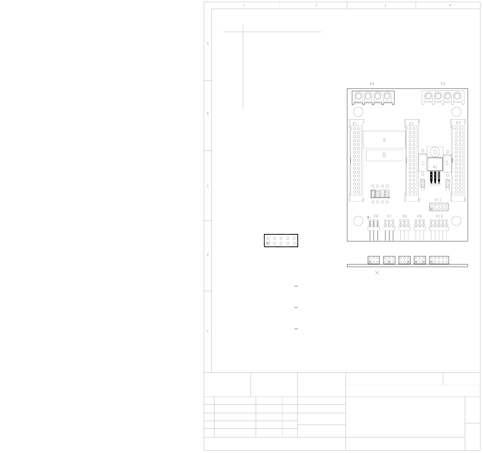
00335413-020101ND3 830 board, potential distributor HS-60
BR4 Jumper inserted
BR5 Not inserted
BR6 Open
BR7 Jumper inserted
BR8 Jumper inserted
BR9 Not inserted
BR10 Not inserted
BR11 Not inserted
BR12 Not inserted
01
51 20.05.97
30.10.97
KL
KL
ANL TD Elektronik E
SIEMENS AG
20.05.97
Klose
00335413-020101ND3
HS60 gantry distribution board
830 board
G32918-J0010-B2-*-0017
Mounting diagram, component side
2-layer PC board
1
1
A = ID label
B = Inspection label
Pinch off pin
PinSocket Socket
ModifiedStat. Date Name
Date
Name
Scale 1:1
Sheet
Sh.
To X3, head board 00344487
To X3, X/Y distributor 00335414
Camera illumination
Step motor supply voltage
To X3, servo unit, motor/tacho, DP-axis
To X3, servo unit, motor/Tacho, Z-axis
Not inserted
To X3, servo unit, motor, DR-axis
Supply voltages 5V, ± 15V, 24V
Not inserted
Not inserted
To X8, servo unit, motor, X-axis
To X1, head board 00344487
To X2, head board 00344487
To X4, head board 00344487
Not inserted
To X2, X/Y distributor 00335414
To X1, X/Y distributor 00335414
Assembly
X9
X16
X17
X18
X13
X14
X15
X10
X11
X12
X1
X6
X7
X8
X5
X3
X4
X2
Plug
To X8, servo unit, motor, Y-axisX19
To X6, control unit, PCB cameraX20
To X6, control unit, component cameraX21
To/from gantry distributor/tape cutterX22
To/from tape cutter/gantry distributorX23
To X1, control unit, X-axis track signalsX24
To X3, control unit, DP-axis track signalsX25
To X1, control unit, Z-axis track signalsX26
Not insertedX27
To X5 control unit, DR-axis track signalsX28
Not insertedX29
Not insertedX30
To X50 and/or X51, servo unit, crash signalX31
To X3, control unit, Y-axis track signalsX32
Not usedX33
02 11.11.98 KL
Not insertedBR1
Jumper configuration
BR2 Not inserted
BR3 Jumper inserted
5 - 15
00335414-010101ND4 825 board, X/Y distributor HS-60
A = ID label
B = Inspection label
* Do not mount
G32918-J0004-B001-*-0017
2-layer PC board
Mounting diagram, component side
825 board
HS60 X/Y distribution board
00335414-010101ND4
1
1
SIEMENS AG
25.11.97
Goller
25.11.97
20.02.98
04.03.97
KL
KL
KL51
01
02
Pinch off key pin
Socket Pins
Stat. Modified Date Name
Date
Name
Scale 1:1
Sheet
Sh.
10
X11
To X8, gantry distributor 00335413
To X6, gantry distributor 00335413
To X7, gantry distributor 00335413
AssemblyConnector
X3
X2
X1
3 Track A
Key
Track N
Track N
9
8
+ 5 V
Track B
Track B
DGND
5
7
6
4
Track A
Analog GND1
2
Y-motorX4
X-motorX5
Not usedX6
Proximity switch 2, Y-axisX7
Proximity switch 1, Y-axisX8
Distance sensorX9
Y-axis track signalsX10
Test connector for Y-axis track signalsX11
97531
10 8 462