circuit of HS60.pdf - 第182页
6 - 3 0034574 0-020 101ND3 HS-60 pneu matic syst em, layo ut f. pneum atic labels NN ± N 1 A3 1710xxx X xxxx xxx xx P Tiefe:0,3/ 2-5 um c hemisch vernickelt 50 20 1 0034 5740-020101ND3 1:1 Scotchca l 3698-E 19.01. 99 Rie…
6 - 2
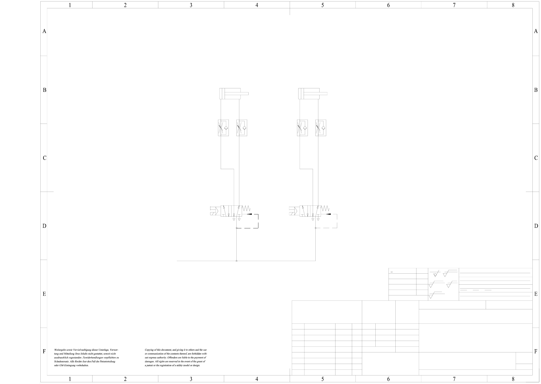
00324065-020102XD3 SIPLACE tape cutter, pneumatically operated
SF
1
00324065-020102XD3
Tape cutter, pneumatically operated
Siplace HS60
18.11.97
Berndl
----
nn.nn.nn
23.02.98
Bern
Name
Status
Date
DS 01
DS 02
new
Pressure entered
Modified
Dimensional variations
Dimension.variations:
Degree of accuracy
medium
acc. to ISO 2768 mH
NameDate
Stand.
Author
Check.
Main no.
(Drawing number)
Format
Scale
(Material, semifinished products)
(Model or swage no.)
(Unmachined part no.)
Drawings 2/A
5.2 bar
2-5 µm chemisch vernickelt
Tiefe:0,3/
1710xxx Xxxxx xxx xx P
A3
1
NN ± N
()
Valve 1
ba
2
3
4
1
5
Valve 2
ba
2
3
4
1
5
Compressed air supply
of servicing unit
machine
Cyl.1
Ø 40 ; Stroke 30
Cyl.2
Ø 40 ; Stroke 30
Sheet
Sh.
Hierzu gehoert
Koordinatenliste:
R 1
z
R 6,3
z
R 25
z
R 100
z
einsatzgehaertet
gehaertet HRc
Oberfl.:
±0,8
±0,5
±0,3
±0,2
±0,1
>400...1000
>120...400
>30...120
>6...30
<6
AUT 5
SIEMENS
FS ES US UA
6 - 3
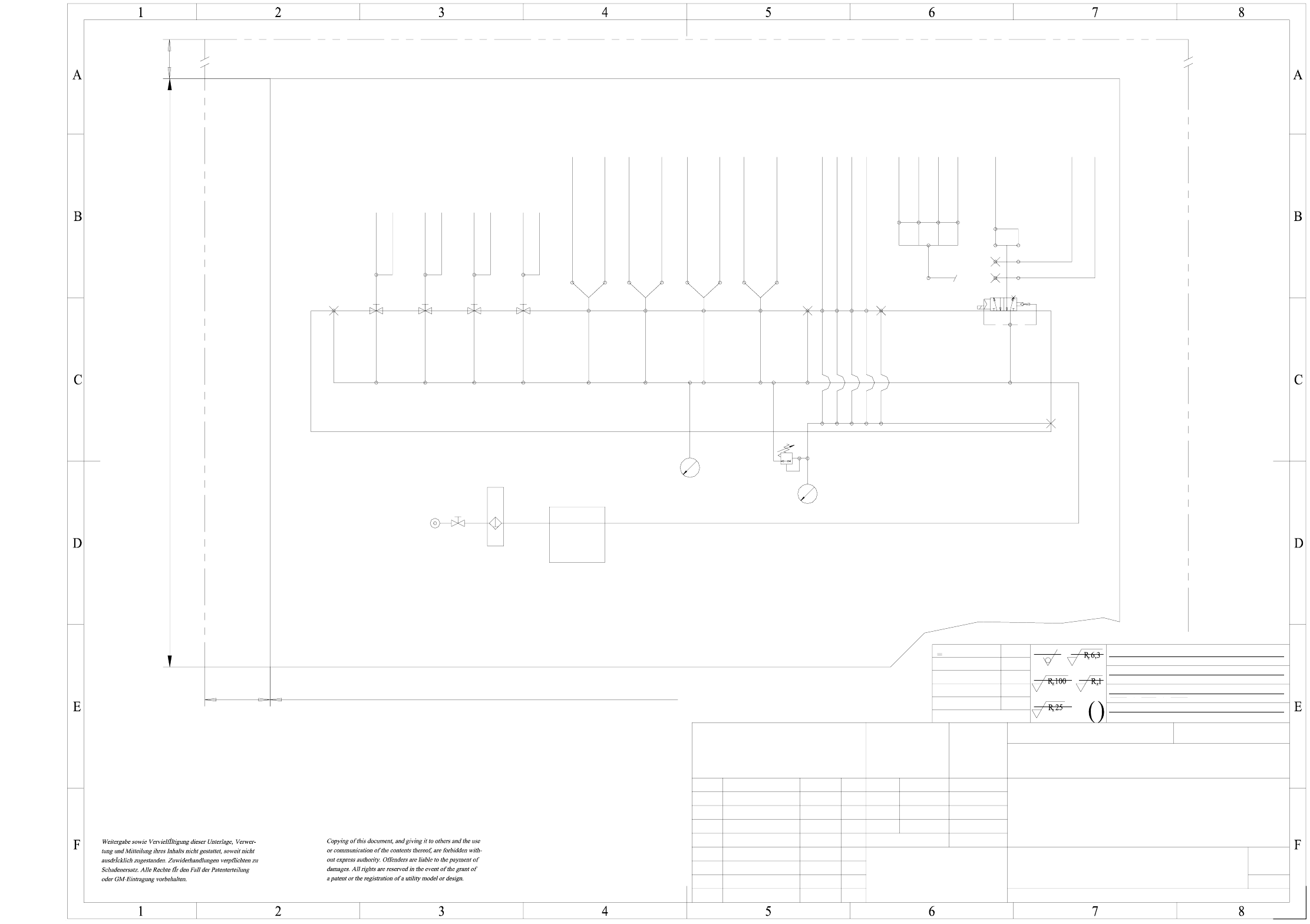
00345740-020101ND3 HS-60 pneumatic system, layout f. pneumatic labels
NN ± N
1
A3
1710xxx Xxxxx xxx xx P
Tiefe:0,3/
2-5 um chemisch vernickelt
50
20
1
00345740-020101ND3
1:1
Scotchcal 3698-E
19.01.99 Ried
FSUA
SIEMENS
PL EA
<6
>6...30
>30...120
>120...400
>400...1000
±0,1
±0,2
±0,3
±0,5
±0,8
Oberfl.:
gehaertet HRc
einsatzgehaertet
Hierzu gehoert
Koordinatenliste:
B10
B5.4 B5.1 B5.2 B5.3 B13.2 B13.1 B12.2 B12.1 B11
B7 B4 B6
B16.4
B16.1
B16.2
B16.3
B17
B1
B2
B8
260
180
Bulk case
Component table
Nozzle
changer Feeder
Compressed air store
PCB stopper
(Option)
Tape
cutter
BCF 4
BCF 1
BCF 2
BCF 3
Sector 4
Sector 3
Table 3
Sector 1
Table 4
Table 1
Table 2
Sector 2
Gantry 2
Gantry 4
Gantry 1
Spare
Gantry 3
Left track 2
Left track 2
Right track 1
Right track 1
Sector 1/2
Sector 3/4
Valve block
p = 5.2 bar
Filter
Sentronic valve
p = 2.5 ±0.5 bar
(at 950Nl/min
compressed-air consumption)
p min = 6.5 bar
Fit on the inside of door
of assembly 00330349-02
Status Modified Date Name
DS 01 new nn.nn.nn ----
FS 02 HHS60 09.05.01 Fu.
Dimension. variations:
Degree of accuracy
medium
acc. to ISO 2768 mH
Date
Name
Author
Check.
Stand.
(Drawing number)
Main no.
HS60 Pneumatic system
Layout for pneumatic label
(Material, semifinished products)
(Unmachined part no.)
(Model or swage no.)
Farbe Al RAL 9006
Scale
Format
Dimensional variations
Sheet
Sh.
FS PS DS
Contour of 00330349-02
6 - 4
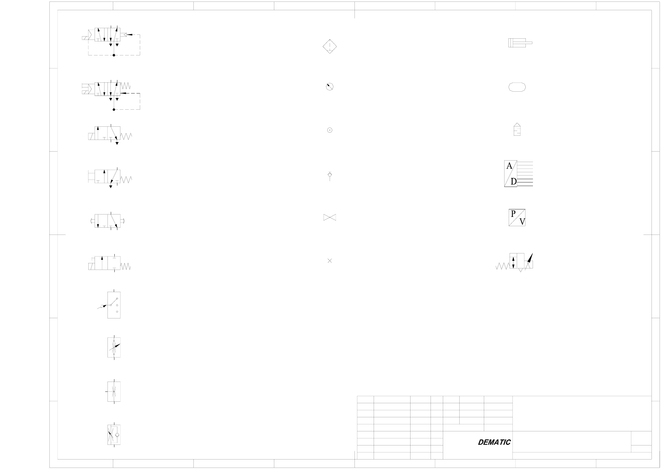
00329906-010101EX3 Pneumatic symbols
8
Sheet
Sh.
12 3 4 765
F
E
D
C
A
B
F
E
D
C
A
B
12 3 4 8765
SD EA
SIEMENS
FS ES US UA S F
1
00329906-010101EX3
Pneumatic symbols
01.07.2001
Hi
Hi
01.07.01
Name
Status
Date
DS 01
new
Modified
NameDate
Stand.
Author
Check.
Main no.
(Drawing number)
with pneumatic spring return
with mechanical spring return
5/2-way solenoid valve with manual override
3/2-way solenoid valve without manual override
with mechanical spring return
2/2-way solenoid valve with manual override
with mechanical spring return
1
5/2-way solenoid valve without manual override
Plug Regulator with exhaust
Pressure / voltage converter
Analog / digital converter
Silencer
Air reservoir
Double acting cylinder
with manual draining
53
24
1
1
53
42
A
RP
ab
A2
R3 P1
b
a
HS60
3/2-way valve, manually operated
by push-button
3/2-way valve, manually operated
Electrical switch
with mechanical spring return
Flow control valve, adjustable
Flow control valve
Flow control valve with flow adjustable in one direction
Quick acting coupling uncoupled,
Pressure source
Filter with water separator
Pressure gauge
closed by non-return valve
Shut-off valve